6
STCS ed 07/02 CAESAR Star
Technical Documentation
Technical Documentation
The circuit consists of an atmospheric burner and a
modulating type valve for gas combustion and gas flow
adjustment respectively.
Operation.
When the main coils (3) are energised, both inner val-
ve shutters open, allowing the gas to flow towards the
burner.
The flow rate/outlet pressure is regulated by means of
the gas valve stabiliser and the modulation coil (1).
By means of the burner nozzles (6), the fuel is injected
into the venturi pipes (ramps) inside which the air-gas
mix is obtained that is ignited by the spark from the
ignition electrode (5).
Modulating gas valve.
The gas valve (SIT 845) features two main coils (3)
and a modulation coil (1) controlled by the modulation
board.
The maximum and minimum outlet pressure settings
can be made on this valve (see gas adjustments).
Main electrical coils (3).
Two coils of the ON-OFF type energised (230V AC)
by the adjustment board when the burner has to be
ignited.
These are electrically connected in parallel and
energised by mains power through a special connec-
tor (2).
Modulation coil (1).
This is a low-voltage coil controlled by the modulation
board.
This controls the gas valve stabiliser and permits
changing the outlet pressure in a way proportionate to
the DC signal that runs through it.
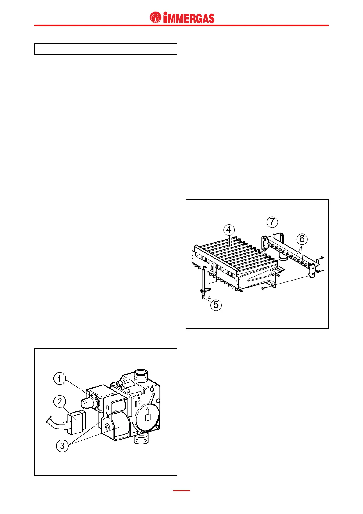
Gas circuit.
Burner.
The burner consists of 12 horizontal venturi pipes (4)
in which the gas is injected by an equal number of
nozzles (6) mounted on the special header (7).
Ignition occurs by means of the adjustment board which
controls the ignition/detection electrode (5).
Ignition and detection electrode (5).
During ignition, this is controlled by the adjustment
board which produces an electrical charge between
its end and the burner surface that ignites the air-gas
mix.
When the burner is on, it also detects the flame on the
burner enabling the adjustment board to conclude the
ignition cycle and change the gas pressure according
to need.
This is positioned on the front of the burner in line with
the centre ramp.