7
STCS ed 07/02 CAESAR Star
Technical Documentation Technical Documentation
Gas adjustments.
Max and minimum gas pressure adjustments can be
made by means of the gas valve respecting the values
shown on the tables relating to the type of
corresponding gas.
Measurements are made using a U-shaped differen-
tial pressure gauge connected to a “Y” to be placed in
between in the small silicone tube connecting the gas
valve to the sealed chamber and to the gas valve outlet
pressure point.
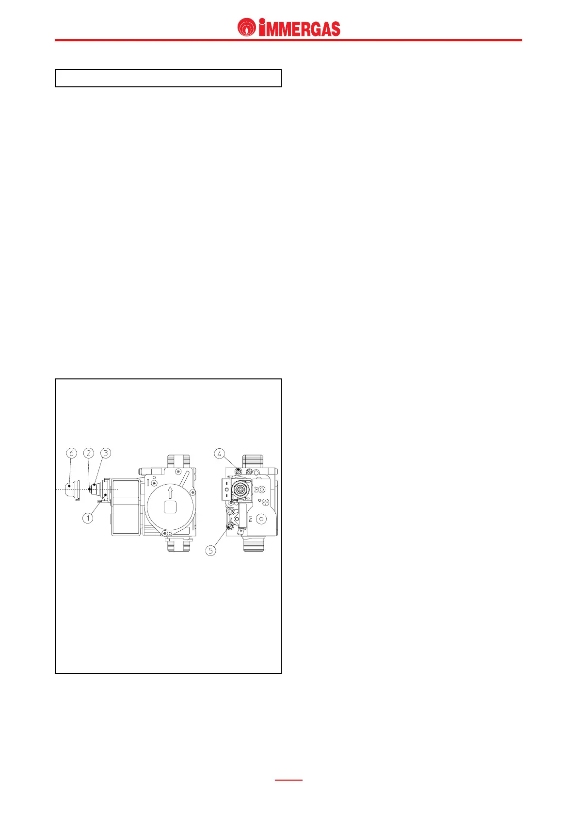
Valve Sit 845.
Maximum pressure setting.
Draw d.h.w. after setting the temperature switch at
maximum.
Turn the brass nut (3) clockwise to increase the
pressure to the burner and anticlockwise to decrease
it.
Adjusting minimum pressure
(to be done after adjusting max pressure).
After interrupting power to the modulation coil, turn the
crosshead screw (2) clockwise to increase pressure
to the burner and anticlockwise to decrease pressure.
Key:
1 - Coil
2 - Minimum output setscrew
3 - Maximum output setscrew
4 - Gas valve outlet pressure point
5 - Gas valve inlet pressure point
6 - Protection cap
Valvola Sit 845
Changing type of gas.
Adaptation to a type of gas different to that for which
the boiler is intended, can be done by using the special
kits (natural gas or LPG).
The changeover consists in replacing the burner
nozzles and in moving to the modulation board of the
“NATURAL GAS- LPG” (S1) bridge.
The minimum and maximum pressures are then set
on the gas valve in the way described above.
The burner ignition pressure is not adjusted
because the type of board operation does not require
such setting (see modulation board operation).
NOTE: any changes made to enable the unit to use
G110 gas (town gas), besides the use of a special
nozzle kit and performance of the same operations
indicated above, also requires shifting jumper switch
“S1” onto switch “S2” on the electronic board (see
modulation board adjustments).