14
STCS ed 07/02 CAESAR Star
Technical Documentation
Technical Documentation
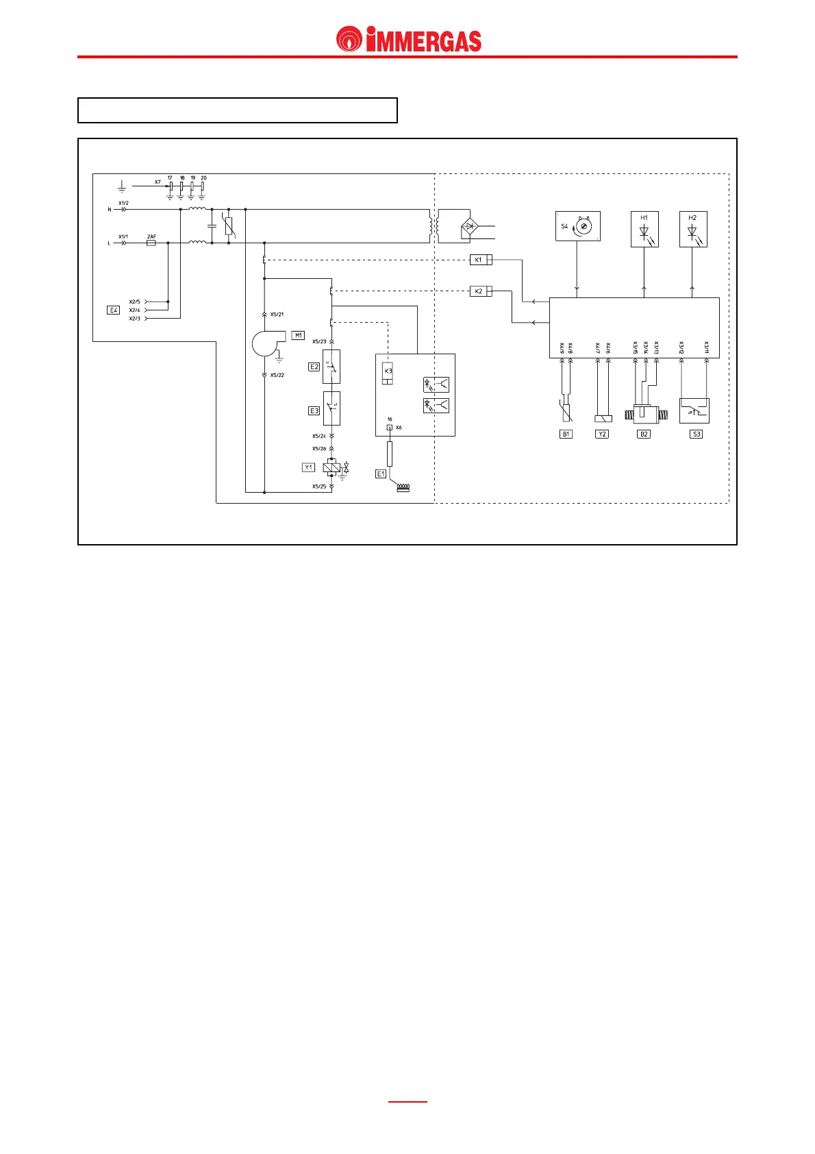
CAESAR Star electrical circuit.
Operation.
When master switch (S4) is in ON position, it powers
the low-voltage circuit and enables appliance
operation.
If hot water is run the flow measuring device (B2) trips
and this gives the signal for burner ignition.
Afterwards, if the temperature detected by the d.h.w.
NTC sensor (B1) is below that set on the control panel
by means of the d.h.w. potentiometer (S4) the board
starts the fan (M1) and commands relay K1.
The consequent closing of the fume pressure switch
(S3) results in the adjustment circuit powering relay
K2.
This way the board ignition circuit is enabled (IGNITION
SECTION) which first of all commands the ignition/
detection electrode (E1) and then excites relay K3.
With a signal from the overheating thermostat (E3) and
limit thermostat (E2), closing of relay K3 contact powers
both main coils of gas valve (Y1).
Burner ignition is detected by ignition/detection
electrode (E1).
IGNITION
SECTION
COMMAND LOGIC MICROPROCESSOR
MAINS
VOLTAGE
LOW
VOLT.