8
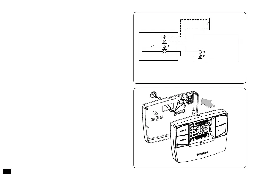
3) To make the electrical connections (g. 4) do not operate
when the boiler is live. e connection must be made at
the clamps envisioned for the connection to the room
thermostat.
e jumper on clamps 40 and 41 of the boiler
P.C.B. (if present) must also be eliminated.
Note: refer to the electrical connections stated in the boiler
instruction book.
e connection to the boiler is made using two wires (g.
5) with minimum section of 0.50 mm
2
and maximum of
1.5 mm
2
.
N.B: for correct installation prepare a dedicated line
for the connection of the CRONO 7 according to the
Standards in force regarding electrical systems.
If this is not
possible interference due to other electric cables could cause
malfunctioning of the CRONO 7 remote control itself.
4) Insert 2 1.5V AA batteries (not supplied) into the relevant
housing (g. 3).
5) Fix the body of the CRONO 7 remote control to the support
template, engaging it with pressure and using the two screws
provided (Fig. 3).
Fig. 5
Fig. 4
CRONO 7
Telephone control
(optional)
BOILER
Connect the CRONO 7 to the boiler
clamps envisioned at the connection
with the room thermostat (see boiler
instruction book).
ere is no need to respect
the polarity of the connection
between CRONO 7 and boiler.