43
4
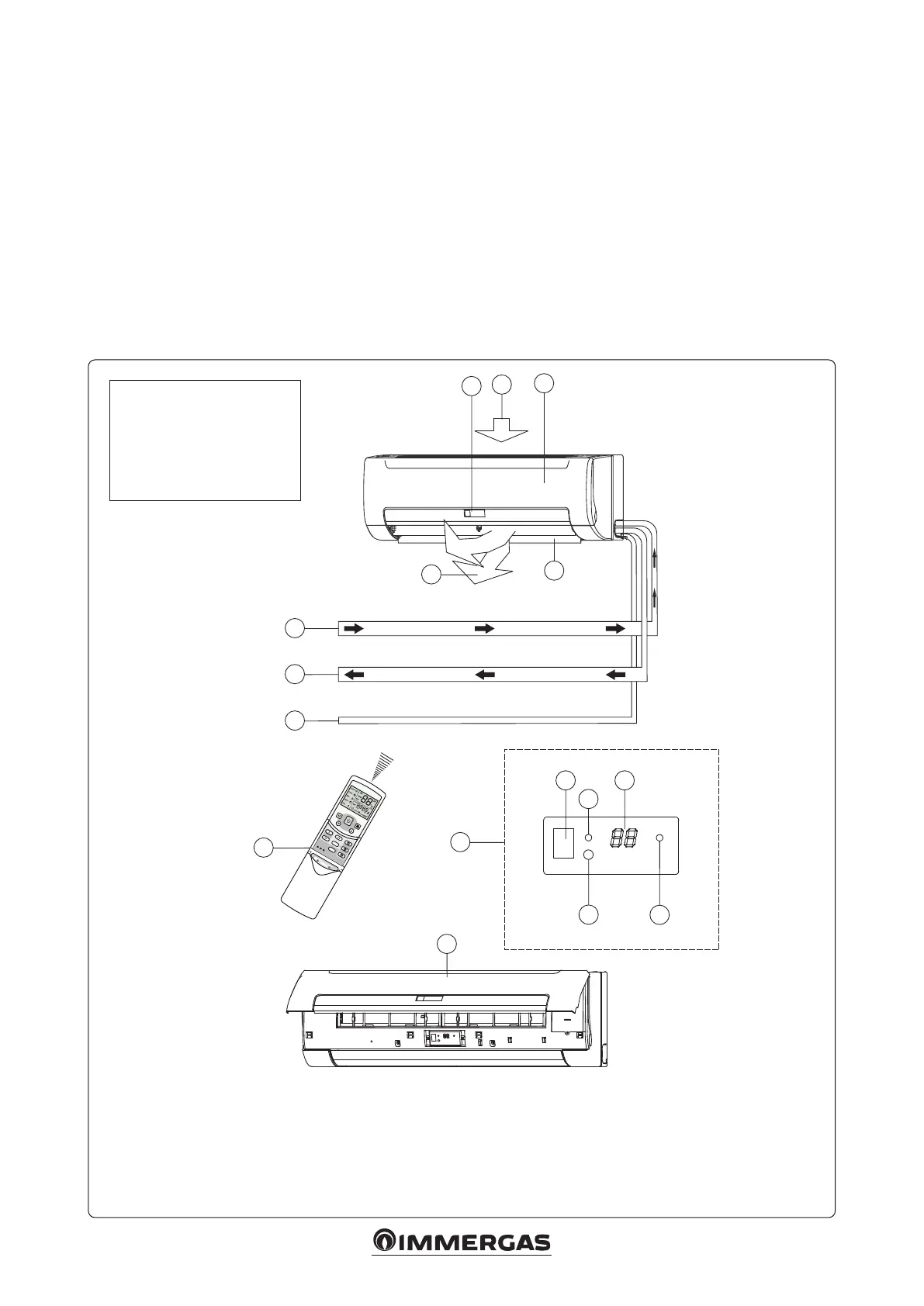
2.4 COMPONENTS.
Key:
1 - Air inlet
2 - Front panel
3 - Display
4 - Air outlet
5 - Horizontal ns
Open the front panel to see the temporary button for the
display panel (14 Fig. 4).
is function is used to temporarily start the unit if the remo-
te control is not positioned correctly or if the batteries are at.
Two modes can be selected with the “TEMPORARY” button:
“AUTO” and “FORCED COOL”. When the button is pressed,
the fan coil will run in the following order: AUTO, FORCED
COOL, OFF and then AUTO again.
• AUTO
e OPERATION LED is on and the fan coil runs in
AUTO mode. e remote control works based according
to the signal received.
• FORCED COOL
e OPERATION LED ashes, the fan coil switches to
AUTO mode aer forced cooling with a HIGH fan speed
for 30 minutes. e remote control is not active.
• OFF
e OPERATION LED turns o. e fan coil is OFF, while
the remote control is reactivated.
Note: for the remote control instructions, see chapter 4.1
“Remote controller”.
6 - Remote control
7 - Water inlet pipe
8 - Water return pipe
9 - Drain pipe
10 - Operation LED
11 - Front panel
12 - Infrared signals receiver
13 - Temperature display
14 - “Temporary” button
15 - Timer insertion LED
11
1
2
3
4
5
6
7
8
9
3
12 13
14
10
15
NOTE
e device is equipped with
a 3-way valve.
It is recommended to set
the balancing valves on the
hydraulic circuit