15
C
82
C
42
C
52
1-24
C
82
1-21
1-22
1-23
1
4
7
9
5
5
6
7
8
3
2
S
A
INSTALLERUSERMAINTENANCE TECHNICIAN
Maximum usable lengths
(including intake terminal with grill and two 90° bends)
NON-INSULATED PIPE INSULATED PIPE
Drain (metres) Intake (metres) Drain (metres) Intake (metres)
1 36.0* 6 29.5*
2 34.5* 7 28.0*
3 33.0* 8 26.5*
4 32.0* 9 25,5*
5 30.5* 10 24.0*
* e air intake pipe can be increased to 2.5 metres if the exhaust bend
is eliminated, 2 metres if the air intake bend is eliminated, 4.5 metres
eliminating both bends.
11 22.5*
12 21.5*
Attention: the boiler is designed to evacuate
the combustion products up to a maximum
extension of 27 linear metres from the exhaust,
with 1 m plus 90° bend at the intake. If the
installation requires a development of the ue
to the discharge that exceeds the recommended
12 m, due consideration must be given to the
formation of condensate that could take place
inside the pipe and insulated ue kits “NOT for
condensing boilers” must be used.
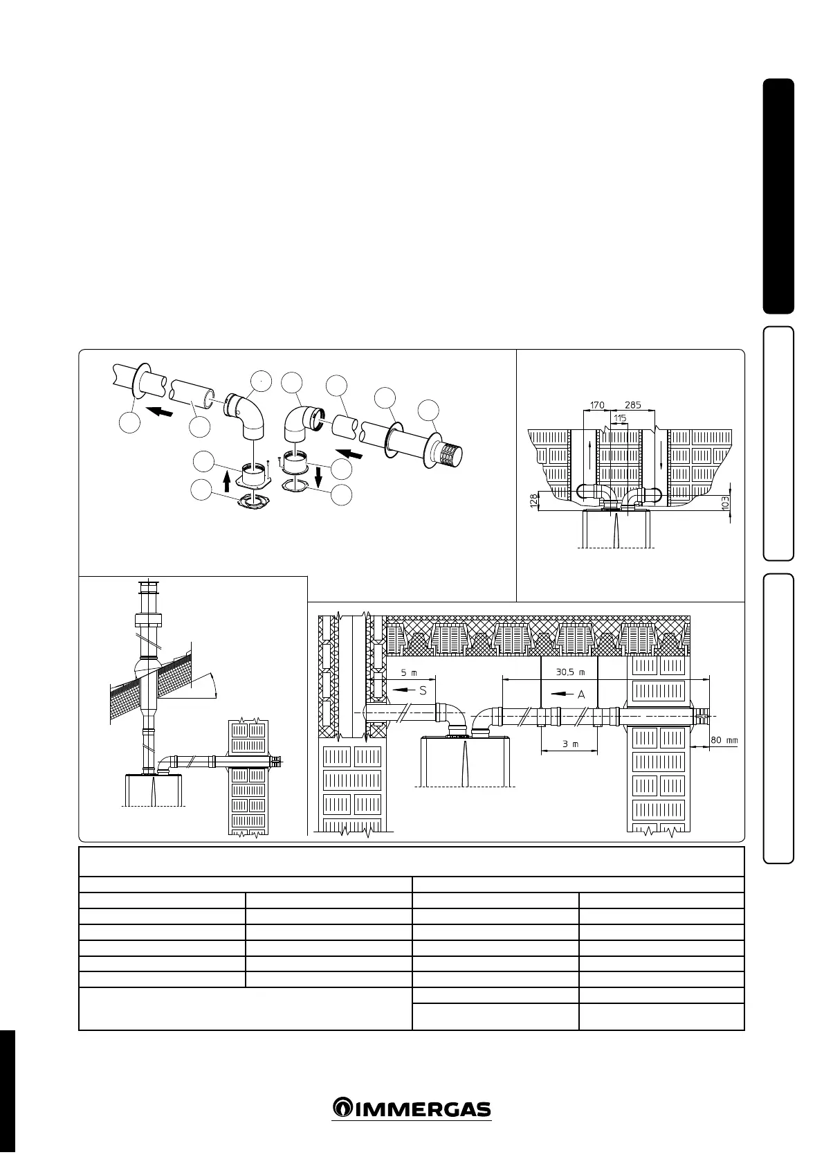
1.13 SEPARATOR KIT INSTALLATION.
Type C configuration, sealed chamber and
fan assisted.
This kit allows air to come in from outside
the building and the exhaust to exit from the
chimney, ue or intubated duct through divided
ue exhaust and air intake pipes. Combustion
products are expelled from pipe (S). Air is taken
in through pipe (A) for combustion. Both ducts
can be routed in any direction.
Separator kit Ø 80/80. Kit assembly (Fig. 1-21):
install the ange (4) on the central hole of the
boiler, interposing the gasket (1) and tighten
with the at-tipped hex screws included in the
kit. Remove the at ange present in the lateral
hole with respect to the central one (according to
needs) and replace it with the ange (3), position-
ing the gasket (2) already present in the boiler and
tighten using the supplied self-threading screws.
Fit the male end (smooth) to the bends (5) in the
female end of the anges (3 and 4). Fit the intake
terminal (6) with the male section (smooth) in
the female section of the bend (5) up to the end
stop, ensuring that the internal and external wall
sealing plates are tted. Fit the exhaust pipe (9)
with the male end (smooth) to the female end
of the bend (5) up to the stop; making sure that
the internal wall sealing plate has been tted, this
will ensure sealing and joining of the elements
making up the kit.
• Installation clearances (Fig. 1-22). e mini-
mum installation clearance measurements of
the Ø 80/80 separator terminal kit have been
stated in some limit conditions.
• Figure 1-23 shows the conguration with verti-
cal exhaust and horizontal intake.
• Extensions for separator kit Ø 80/80. e max.
vertical straight length (without bends) usable
for Ø 80 intake and exhaust pipes is 41 metres
of which 40 intake and 1 exhaust. is total
length corresponds to a resistance factor of
100. e total usable length obtained by sum-
ming the Ø 80 intake and exhaust pipe lengths
can reach, as a maximum, the values provided
in the following table. If mixed accessories or
components are used, the maximum extension
can be calculated by using a resistance factor
for each component or its equivalent length.
e sum of these resistance factors must not
exceed 100.
Max 45%
e kit includes:
N°1 - Exhaust gasket (1)
N°1 - Female intake ange (3)
N°1 - Flange gasket (2)
N°1 - Female exhaust ange (4)
N°2 - 90° bend Ø 80 (5)
N°1 - Intake terminal Ø 80 (6)
N°2 - Internal rings (7)
N°1 - External grey wall sealing plate (8)
N°1 - Exhaust pipe Ø 80 (9)
STD.002998/004