8
45
31
58
1-4
1-6
1-5
INSTALLERUSERMAINTENANCE TECHNICIAN
MAX
MIN
Position of the central heating tem-
perature user adjustment
1.7 REMOTE CONTROLS AND ROOM
CHRONOTHERMOSTATS
OPTIONAL.
e boiler is prepared for the application of room
chrono-thermostats or remote controls, which
are available as optional kits (Fig. 1-4).
All Immergas chrono-thermostats are connected
with 2 wires only. Carefully read the user and
assembly instructions contained in the acces-
sory kit.
• On/O digital Immergas chrono-thermostat.
e chrono-thermostat allows:
- set two room temperature value: one for
daytime (comfort temperature) and one for
night-time (reduced temperature);
- set a weekly program with four daily switch
on and switch o times;
- select the required operating mode from the
various possible alternatives:
- manual mode (with adjustable tempera-
ture).
- automatic mode (with set program).
- forced automatic mode (momentarily
changing the temperature of the automatic
program).
e chrono-thermostat is powered by two 1.5V
LR 6 type alkaline batteries.
• Comando Amico Remoto remote control
V2
(CAR
V2
) with chrono-thermostat function.
In addition to the functions described in the
previous point, the CAR
V2
panel enables the
user to control all the important information
regarding operation of the appliance and the
heating system with the opportunity to easily
intervene on the previously set parameters,
without having to go to where the appliance
is installed. e panel is provided with self-
diagnosis to display any boiler functioning
anomalies. The climate chrono-thermostat
incorporated into the remote panel enables
the system ow temperature to be adjusted to
the actual needs of the room being heated, in
order to obtain the desired room temperature
with extreme precision and therefore with
evident saving in running costs. e CAR
V2
is
fed directly by the boiler by means of the same 2
wires used for the transmission of data between
the boiler and device.
Important: if the system is subdivided into zones
using the relevant kit, the CAR
V2
must be used
with its climate thermostat function disabled, i.e.
it must be set to On/O mode.
Comando Amico Remoto Remote Control
V2
or On/O chrono-thermostat electrical con-
nections (Optional). e operations described
below must be performed aer having removed
the voltage from the appliance. Any thermostat
or On/O environment chrono-thermostat must
be connected to clamps 40 and 41 eliminating
jumper X40 (Fig. 3-2). Make sure that the On/
O thermostat contact is of the “clean” type, i.e.
independent of the mains voltage, otherwise the
P.C.B. would be damaged. Any Comando Amico
Remoto Remote Control
V2
must be connected to
clamps 41 and 44 eliminating jumper X40 on the
P.C:B., paying attention not to invert the polarity
in the connections (Fig. 3-2).
Important: if the Comando Amico Remoto
Remote Control
V2
or any other On/O chrono-
thermostat is used, arrange two separate lines in
compliance with current regulations regarding
electrical systems. No boiler pipes must ever be
used to earth the electric system or telephone
lines. Ensure elimination of this risk before mak-
ing the boiler electrical connections.
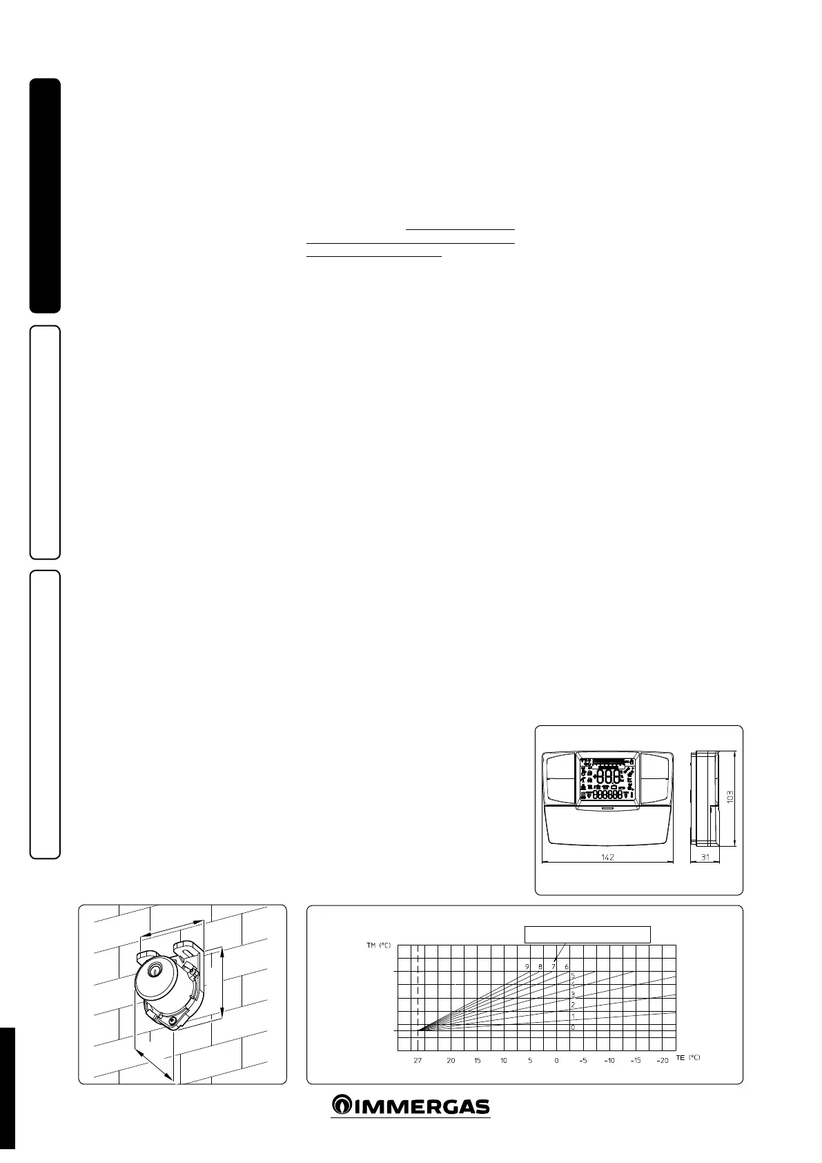
1.8 EXTERNAL PROBE OPTIONAL.
e boiler is designed for the application of the
Room ermostat (Fig. 1-5) which is available
as an optional kit. Refer to the relative instruc-
tion sheet for positioning of the external probe.
e probe can be connected directly to the boiler
electrical system and allows the max. system
ow temperature to be automatically decreased
when the external temperature increases, in
order to adjust the heat supplied to the system
according to the change in external temperature.
e external probe always acts when connected
independently from the presence or type of room
thermostat used. e correlation between system
ow temperature and outdoor temperature is de-
termined by the position of the selector switch on
the boiler control panel according to the curves
shown in the diagram (Fig. 1-6). e electric con-
nection of the external probe must be made on
clamps 38 and 39 on the boiler P.C.B. (Fig. 3-2).
STD.002998/004
 Loading...


