9
1-7
1-8
1-9
INSTALLERUSERMAINTENANCE TECHNICIAN
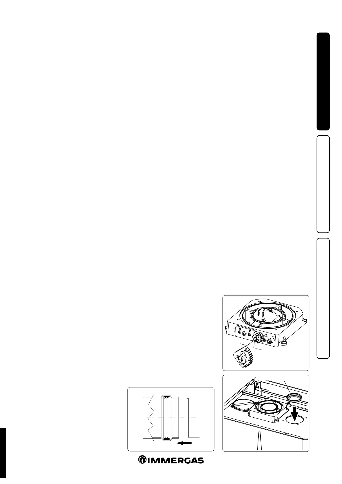
DIAPHRAGM
1.9 IMMERGAS FLUE SYSTEMS.
Immergas supplies various solutions separately
from the boilers regarding the installation of air
intake terminals and ue extraction, which are
fundamental for boiler operation.
Attention: the boiler must only be installed
together with an original Immergas air intake
and ue gas exhaust system, except for the C6
conguration, in compliance with the stand-
ards in force. is system can be identied by
an identication mark and special distinctive
marking bearing the note: “not for condens-
ing boilers”.
e ue exhaust pipes must not be in contact with
or be near to ammable materials. Moreover,
they must not pass through buildings or walls
made of ammable material.
See following paragraphs for the detailed descrip-
tion of the kits available
Positioning of double lip seals. For correct
positioning of lip seals on elbows and exten-
sions, follow the direction of assembly given in
gure (Fig. 1-7).
• Resistance factors and equivalent lengths. Each
ue component has a Resistance Factor based
on experimental tests and specied in the table
below. e Resistance Factor for individual
components is independent from the type of
boiler on which it is installed and has a dimen-
sionless size. It is however, conditioned by the
temperature of the uids that pass through the
pipe and therefore, varies according to applica-
tions for air intake or ue exhaust. Each single
component has a resistance corresponding to
a certain length in metres of pipe of the same
diameter; the so-called equivalent length,
can be obtained from the ratio between the
relative Resistance Factors. All boilers have an
experimentally obtainable maximum Resistance
Factor equal to 100. e maximum Resistance
Factor allowed corresponds to the resistance
encountered with the maximum allowed pipe
length for each type of Terminal Kit. This
information allows calculations to be made to
verify the possibility of setting up various ue
congurations.
• Coupling extension pipes and concentric
elbows. To install push-tting extensions with
other elements of the ue, proceed as follows:
Install the concentric pipe or elbow with the
male side (smooth) on the female side (with lip
seal) to the end stop on the previously installed
element in order to ensure sealing eciency of
the coupling.
Attention: if the exhaust terminal and/or
concentric extension pipe needs shortening,
consider that the internal duct must always
protrude by 5 mm with respect to the external
duct.
• N.B.: for safety purposes, do not obstruct the
boiler intake/exhaust terminal, even temporar-
ily.
• N.B.: during the installation of the horizontal
pipes one must install a section clamp with
gusset every 3 metres for non-insulated pipes
and one every 2 metres for insulated pipes.
Flue gas separator adjustment. For correct
functioning of the boiler it is necessary to regu-
late the ue gas shutter positioned on the air/ue
gas sample points (Fig. 1-8).
Adjustment is carried out by loosening the
front retainer screw and moving the indicator
to the correct position, aligning its value to the
horizontal reference. Once adjustment has been
performed, tighten the screw to x the separator.
e appropriate adjustment is chosen based on
type of pipe and its extension: this calculation
can be made using specic tables.
Intake diaphragm installation. For correct
boiler functioning with Ø 80 separator kits and
drain measuring > 1 m a diaphragm must be
installed on the sealed chamber intake hole and
before the intake pipe (Fig. 1-9). e appropriate
diaphragm is chosen based on type of pipe and
its maximum extension: this calculation can be
made using the tables below:
N.B.: the diaphragms are supplied together with
the boiler as standard.
STD.002998/004
 Loading...


