9
STMiN3E ed 09/11 MINI NIKE 3 E
Technical Documentation
Technical Documentation
e primary circuit, with relative control and safety devices,
starts up every time there is a central heating or domestic
hot water request.
Functioning (see MINI NIKE 24)
e heat contained in the ue produced by combustion is
absorbed by the copper blades of the water-air heat exchanger
(8) which, then transfers the heat to the water that circulates
inside by the boiler pump (14).
e water is either sent directly into the system or it can be
deviated inside the STAINLESS steel instantaneous plate heat
exchanger (17).
is depends on the position of the 3-way motorised valve (18),
which allows ow towards the domestic water heat exchanger
(17) in its resting position, or deviates it towards the ow (M)
and return (R) pipes following a request for central heating.
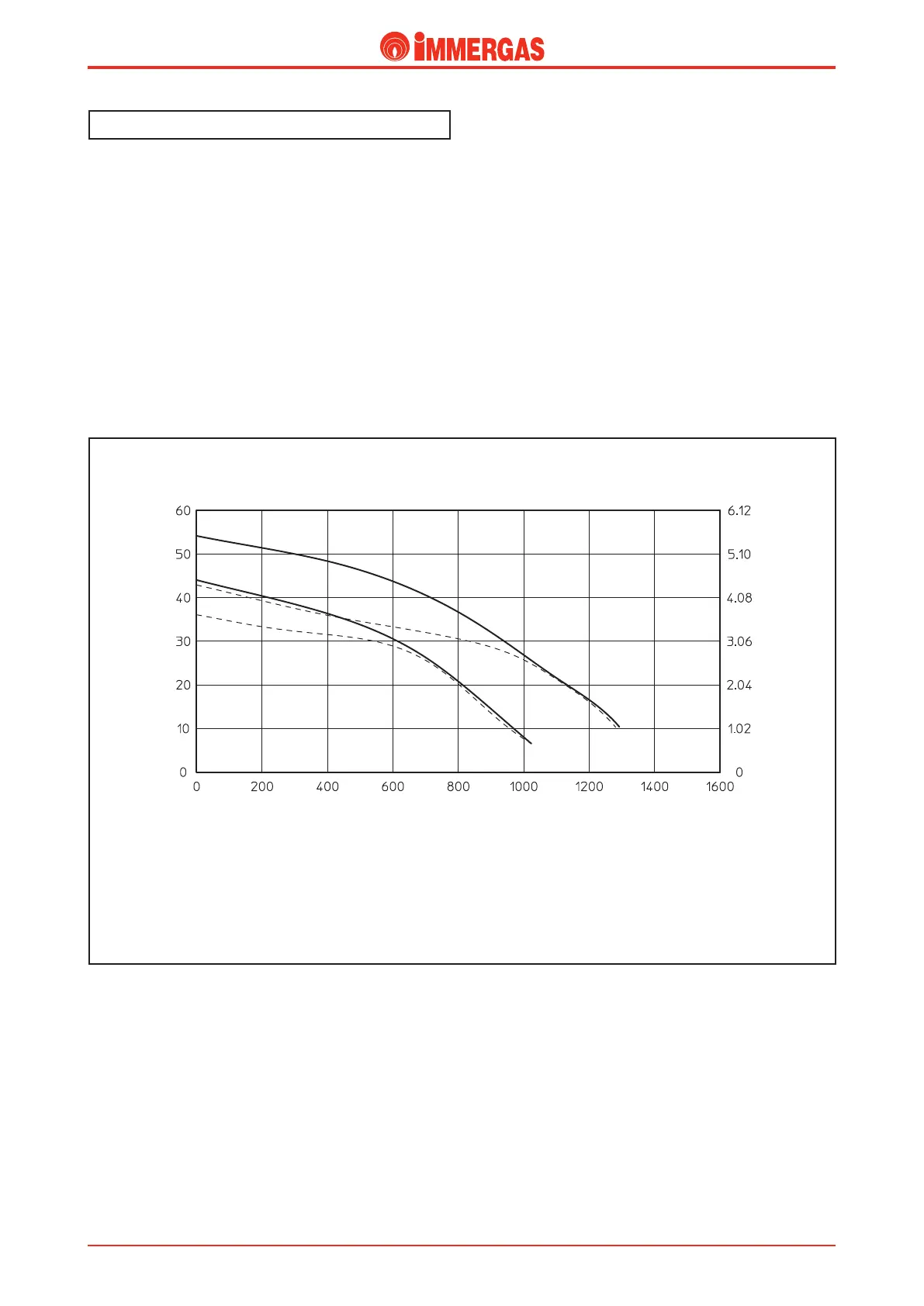
Head ow rate graphics
e progress of the curve that represents the ow rate-head
ratio available to the system depends on the operating speed of
the pump which, according to the position, allows you to set
more or less head on the system. e graph below illustrates
the characteristic curves.
Primary circuit (Boiler Circuit)
A = Head available to the system at maximum speed with by-pass excluded.
B = Head available to the system at maximum speed with by-pass inserted.
C = Head available to the system at second speed with by-pass excluded.
D = Head available to the system at second speed with by-pass inserted.
MINI NIKE 24 - X 24
A
B
Head (m H
2
O)
Flow rate (l/h)
Head (kPa)
C
D