TR
SI
CZ
HU
RO
PL
RU
UA
SK
ES
IE
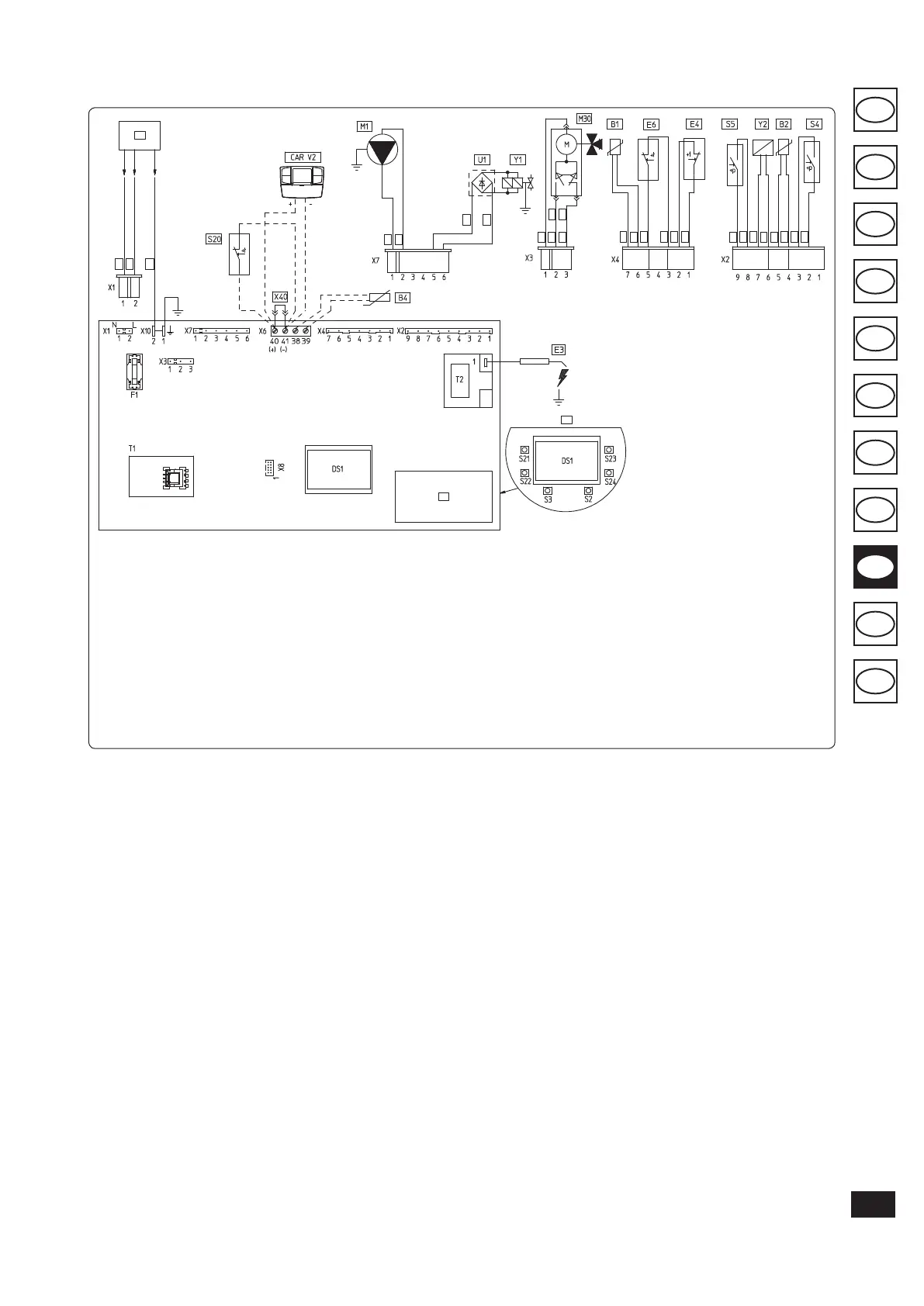
3.2 WIRING DIAGRAM.
Fig. 3-2
Key:
B1 - Flow probe
B2 - Domestic hot water probe
B4 - External probe
CAR
V2
- Comando Amico Remoto remote
control Version 2 (optional)
DS1 - Display
E3 - Ignition and detection electrodes
E4 - Safety thermostat
E6 - Flue safety thermostat
F1 - Phase fuse
M1 - Boiler pump
M30 - ree-way valve
S2 - Selector switch functioning
S3 - Reset block key
S4 - Domestic hot water ow switch
S5 - System pressure switch
S20 - Room thermostat (optional)
S21 - Domestic hot water temperature
increase key
S22 - Domestic hot water temperature
decrease key
S23 - Heating temperature increase key
S24 - Heating temperature reduce key
e boiler is designed for application of a room
thermostat (S20), an On/O room chronother-
mostat, a program timer or a Comando Amico
Remoto remote control
V2
(CAR
V2
). Connect
to clamps 40 - 41 eliminating the jumper X40,
paying attention not to invert the polarity if the
CAR
V2
is installed.
e connector X8 is used for the connection
of the Virgilio Palmtop in the microprocessor
soware updating operation.
3.3 TROUBLESHOOTING.
N.B.: Maintenance must be carried out by a
qualied technician (e.g. Immergas Technical
Aer-Sales Assistance Service).
- Smell of gas. Caused by leakage from gas circuit
pipelines. Check sealing eciency of gas intake
circuit.
- Irregular combustion (red or yellow ame).
When the burner is dirty or the boiler lamellar
pack is blocked. Clean the burner or the boiler
lamellar pack.
- Frequent interventions of the over heating
safety thermostat. It can depend on the lack
of water in the boiler, little water circulation
in the system or blocked pump. Check on the
manometer that the system pressure is within
established limits. Check that the radiator
valves are not closed and also the functionality
of the pump.
- e boiler produces condensate. is can be
caused by obstructions of the chimney or ues
with height or section not proportioned to the
boiler. It can also be determined by function-
ing at boiler temperatures that are excessively
low. In this case, make the boiler run at higher
temperatures.
- Frequent interventions of the ue safety ther-
mostat is can be caused by obstructions in
the ue gas circuit. Check the ue. e ue
may be obstructed or by height or section
not suitable for the boiler. Ventilation may be
insucient (see room ventilation point).
- Presence of air in the system. Check opening of
the hood of the special air vent valve (Fig. 1-10).
Make sure the system pressure and expansion
vessel pre-charge values are within the set
limits; the pre-charge value for the expansion
vessel must be 1.0 bar, and system pressure
between 1 and 1.2 bar.
- Ignition block and Chimney block. (See par.
2.6 and 1.3 (electric connection).
5
1
2
6
5
4
3
4
4
5
11
7
7
7
12
12
7
13
13
11
5
7
4
10
10
10
10
9
8
T1 - Low voltage feeder
T2 - Switch-on transformer
U1 - Rectier inside the gas valve
connector (Only available on
Honeywell gas valves)
X40 - Room thermostat jumper
Y1 - Gas valve
Y2 - Gas valve modulator
1 - User interface
2 - N.B.: e user interface is on
the welding side of the boiler
board
3 - 230 Vac 50Hz power supply
4 - Blue
5 - Brown
6 - Yellow/Green
7 - Black
8 - (DHW)
9 - (central heating)
10 - Grey
11 - White
12 - Red
13 - Green