TR
SI
CZ
HU
RO
PL
RU
UA
SK
ES
IE
1
BOILER
INSTALLATION
1.1 INSTALLATION
RECOMMENDATIONS.
e Nike Mini Nike 24 3 E boiler has been de-
signed for wall mounted installation only; they
must be used to heat environments, to produce
domestic hot water and similar purposes.
e wall surface must be smooth, without any
protrusions or recesses enabling access to the
rear part. ey are NOT designed to be installed
on plinths or oors (Fig. 1-1).
Only professionally qualied heating/plumbing
technicians are authorised to install Immergas
gas appliances. Installation must be carried out
according to the standards, current legislation
and in compliance with local technical regula-
tions and the required technical procedures.
Installation of the Mini Nike 24 3 E boiler when
powered by LPG must comply with the rules
regarding gases with a greater density than air
(remember, as an example, that it is prohibited
to install systems powered with the above-men-
tioned gas in rooms where the oor is at a lower
quota that the average external country one).
Before installing the appliance, ensure that it
is delivered in perfect condition; if in doubt,
contact the supplier immediately. Packing ma-
terials (staples, nails, plastic bags, polystyrene
foam, etc.) constitute a hazard and must be kept
out of the reach of children. If the appliance
is installed inside or between cabinets, ensure
sucient space for normal servicing; therefore
it is advisable to leave clearance of at least 3 cm
between the boiler casing and the vertical sides
of the cabinet. Leave adequate space above the
boiler for possible water and ue removal con-
nections. It is just as important that the intake
grids are not obstructed. Keep all ammable
objects away from the appliance (paper, rags,
plastic, polystyrene, etc.). Do not place household
appliances underneath the boiler as they could
be damaged if the safety valve intervenes (if
not conveyed away by a discharge funnel), or if
there are leaks from the hydraulic connections;
on the contrary, the manufacturer cannot be
held responsible for any damage caused to the
household appliances.
In the event of malfunctions, faults or incorrect
operation, turn the appliance o immediately
and contact a qualied technician (e.g. the Im-
mergas After-Sales Assistance centre, which
has specically trained sta and original spare
parts). Do not attempt to modify or repair the
appliance alone. Failure to comply with the above
implies personal responsibility and invalidates
the warranty.
• Installation regulations:
- these boilers cannot be installed in bedrooms
or shower or bathrooms; ey cannot be in-
stalled in rooms with open res without their
own air ow. ey must be installed in rooms
where the temperature cannot fall below 0°C
and must not be exposed to atmospheric
agents.
- Type B open chamber boilers must not be
installed in places where commercial, artisan
or industrial activities take place, which use
products that may develop volatile vapours
or substances (e.g. acid vapours, glues, paints,
solvents, combustibles, etc.), as well as dusts
(e.g. dust deriving from the working of wood,
coal nes, cement, etc.), which may be dam-
aging for the components of the appliance
and jeopardise functioning.
Important: Wall mounting of the boiler must
guarantee stable and ecient support for the
generator.
e plugs (standard supply) are to be used only in
conjunction with the mounting brackets or xing
template to x the appliance to the wall; they only
ensure adequate support if inserted correctly (ac-
cording to technical standards) in walls made of
solid or semi-hollow brick or block. In the case of
walls made from hollow brick or block, partitions
with limited static properties, or in any case walls
other than those indicated, a static test must be
carried out to ensure adequate support.
N.B.: the hex head screws supplied in the blister
pack are to be used exclusively to x the relative
mounting bracket to the wall.
ese boilers are used to heat water to below boil-
ing temperature in atmospheric pressure.
ey must be connected to a central heating
system and hot water circuit suited to their
performance and capacity.
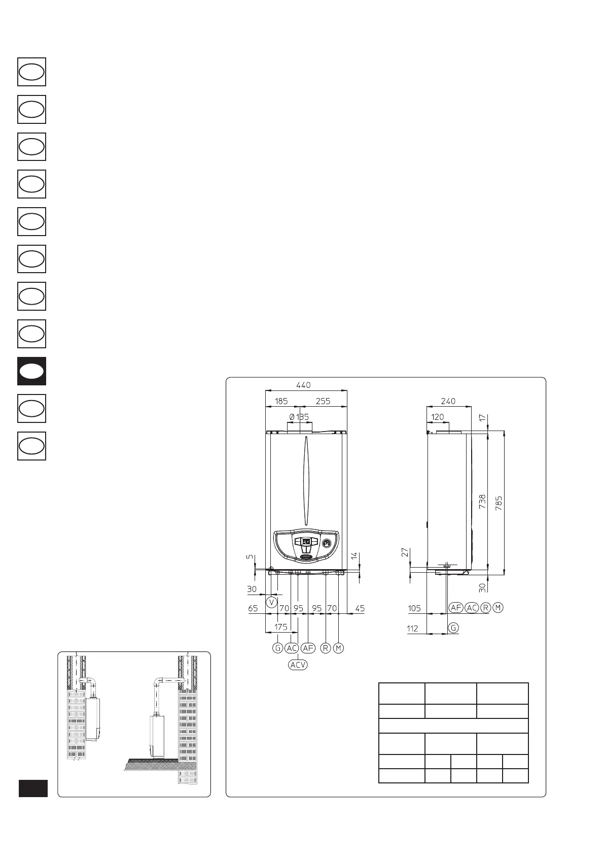
1.2 MAIN DIMENSIONS.
Fig. 1-2
Fig. 1-1
Key:
G - Gas supply
AC - Domestic hot water outlet
ACV - Solar valve kit DHW inlet
(Optional)
AF - Domestic cold water inlet
R - System return
M - System ow
V - Electrical connection
N.B.: connection group (optional)
Height
(mm)
Width
(mm)
Depth
(mm)
785 440 240
CONNECTIONS
GAS
DOMESTIC
HOT WATER
SYSTEM
G AC AF R M
3/4” 1/2” 1/2” 3/4” 3/4”
YES NO
 Loading...