TR
SI
CZ
HU
RO
PL
RU
UA
SK
ES
IE
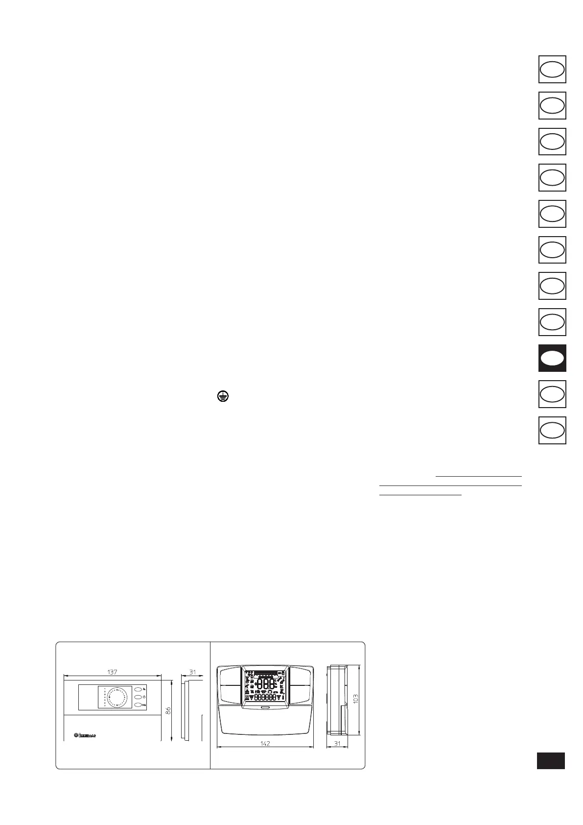
On/O digital chronothermostat
Comando Amico Remoto remote control
V2
(CAR
V2
)
Fig. 1-6
Fig. 1-5
Hydraulic connections must be made in a
rational way using the couplings on the boiler
template. e boiler safety valve outlet must be
connected to an appropriate drain. Otherwise,
the manufacturer declines any responsibility in
case of ooding if the drain valve cuts in.
Important: to preserve the duration of appliance
eciency features, in the presence of water whose
features can lead to the deposit of lime scale,
installation of the “polyphosphate dispenser” kit
is recommended. On the basis of the Standards in
force, it is mandatory to treat the water with over
25 French degrees in the heating circuit and over
15 French degrees for DHW using conditioning
chemicals for powers < 100 kW or with soeners
for powers > 100 kW.
Electrical connection. e Mini Nike 24 3 E
boiler has an IPX4D protection rating for the
entire appliance. Electrical safety of the unit is
reached when it is correctly connected to an
ecient earthing system as specied by current
safety standards.
Important: Immergas S.p.A. declines any re-
sponsibility for damage or physical injury caused
by failure to connect the boiler to an ecient
earth system or failure to comply with the refer-
ence standards.
Also ensure that the electrical installation cor-
responds to maximum absorbed power specica-
tions as shown on the boiler data-plate. Boilers
are supplied complete with an “X” type power
cable without plug. e power supply cable must
be connected to a 230V ±10% / 50Hz mains sup-
ply respecting L-N polarity and earth connection
. is network must also have an omnipolar
circuit breaker with class III over-voltage cat-
egory. When replacing the power supply cable,
contact a qualied technician (e.g. the Immergas
Aer-Sales Technical Assistance Service). e
power cable must be laid as shown. In the event
of mains fuse replacement on the P.C.B., use a
2A quick-blow fuse. For the main power supply
to the appliance, never use adapters, multiple
sockets or extension leads.
1.4 REMOTE CONTROLS AND
ROOM CHRONOTHERMOSTATS
OPTIONAL.
e boiler is prepared for the application of room
chronothermostats or remote controls, which are
available as optional kits.
All Immergas chronothermostats can be con-
nected with 2 wires only. Carefully read the
user and assembly instructions contained in the
accessory kit.
1.3 CONNECTIONS.
Gas connection (Appliance category II
2H3+
).
Our boilers are designed to operate with methane
gas (G20) and LPG. Supply pipes must be the
same as or larger than the 3/4”G boiler tting.
Before connecting the gas line, carefully clean
inside all the fuel feed system pipes to remove any
residue that could impair boiler eciency. Also
make sure the gas corresponds to that for which
the boiler is prepared (see boiler data-plate). If
dierent, the appliance must be converted for op-
eration with the other type of gas (see converting
appliance for other gas types). e dynamic gas
supply (methane or LPG) pressure must also be
checked according to the type used in the boiler,
as insucient levels can reduce generator output
and cause malfunctions.
Ensure correct gas cock connection by follow-
ing the mounting instructions illustrated in
the gure. e gas supply pipe must be suitably
dimensioned according to current regulations in
order to guarantee correct gas ow to the burner
even in conditions of maximum generator output
and to guarantee appliance eciency (technical
specications). e coupling system must con-
form to standards.
Fuel gas quality. e appliance has been designed
to operate with gas free of impurities; otherwise it
is advisable to t special lters upstream from the
appliance to restore the purity of the gas.
Storage tanks (in case of supply from LPG
depot).
- New LPG storage tanks may contain residual
inert gases (nitrogen) that degrade the mixture
delivered to the appliance casing functioning
anomalies.
- Due to the composition of the LPG mixture,
layering of the mixture components may occur
during the period of storage in the tanks. is
can cause a variation in the heating power of
the mixture delivered to the appliance, with
subsequent change in its performance.
Hydraulic connection.
Important: In order not to void the warranty
before making the boiler connections, carefully
clean the heating system on the primary heat
exchanger (pipes, radiators, etc.) with special
pickling or de-scaling products to remove any
deposits that could compromise correct boiler
operation.
In compliance with Standards in force it is man-
datory to treat the water in the heating system
chemically in order to protect the system and
appliance from deposits of lime scale.
• On/O digital chronothermostat (Fig. 1-5).
e chronothermostat allows:
- to set two room temperature values: one
for day (comfort temperature) and one for
night (lower temperature);
- to set up to four on/o dierential weekly
programs;
- to select the required operating mode from
the various possible alternatives:
• permanent functioning in comfort temp;
• permanent functioning in reduced temp;
• permanent functioning in adjustable anti-
freeze temp.
e chronothermostat is powered by two
1.5V LR 6 type alkaline batteries.
• Comando Amico Remoto Remote Control
Device
V2
(CAR
V2
) with climate chronother-
mostat function. In addition to the functions
described in the previous point, the CAR
panel
V2
enables the user to control all the im-
portant information regarding operation of
the appliance and the heating system with the
opportunity of easily intervening on the pre-
viously set parameters without having to go
to the place where the appliance is installed.
e panel is provided with self-diagnosis to
display any boiler functioning anomalies.
e climate chronothermostat incorporated
into the remote panel enables the system ow
temperature to be adjusted to the actual needs
of the room being heated, in order to obtain
the desired room temperature with extreme
precision and therefore with evident saving
in running costs. e chronothermostat is fed
directly by the boiler by means of the same
2 wires used for the transmission of data
between boiler and chronothermostat.
Important: If the system is subdivided into
zones using the relevant kit. the CAR
V2
must
be used with its climate thermostat function
disabled, i.e. it must be set to On/O mode.
Comando Amico Remoto remote control
V2
or
On/O chronothermostat electrical connec-
tions (Optional). e operations described be-
low must be performed aer having removed the
voltage from the appliance. Any thermostat or
On/O environment chronothermostat must
be connected to clamps 40 and 41 eliminating
jumper X40 (Fig. 3-2). Make sure that the On/
O thermostat contact is of the “clean” type,
i.e. independent of the mains supply, otherwise
the electronic adjustment card would be dam-
aged. Any Comando Amico Remoto remote
control
V2
must be connected to clamps 40 and
41 eliminating jumper X40 on the circuit board,
paying attention not to invert the connections
(Fig. 3-2).
Important: if the Comando Amico Remoto
remote control
V2
or any other On/O chrono-
thermostat is used arrange two separate lines in
compliance with current regulations regarding
electrical systems. No boiler pipes must ever be
used to earth the electric system or telephone
lines. Ensure elimination of this risk before
making the boiler electrical connections.
 Loading...