TR
SI
CZ
HU
RO
PL
RU
UA
SK
ES
IE
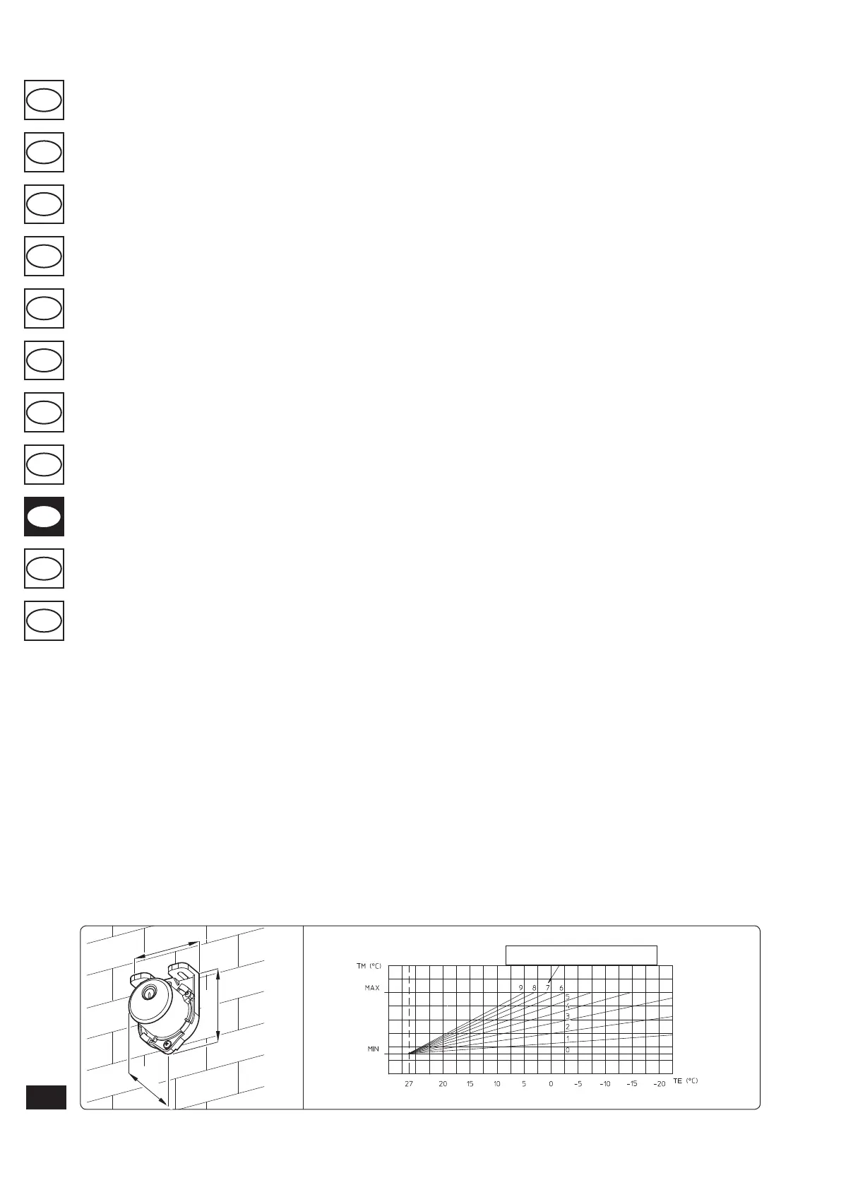
1.5 EXTERNAL PROBE OPTIONAL.
e boiler is prepared for the application of the
external probe (Fig. 1-7), which is available as
an optional kit.
e probe can be connected directly to the boiler
electrical system and allows the max. system
ow temperature to be automatically decreased
when the external temperature increases, in
order to adjust the heat supplied to the system
according to the change in external temperature.
e external probe always acts when connected
independently from the presence or type of room
thermostat used. e correlation between system
ow temperature and external temperature is de-
termined by the position of the selector switch on
the boiler control panel according to the curves
shown in the diagram (Fig. 1-8). e electric con-
nection of the external probe must be made on
clamps 38 and 39 on the boiler P.C.B. (Fig. 3-2).
1.6 VENTILATION OF THE ROOMS.
In the room in which the boiler is installed it is
necessary that at least as much air ows as that
requested for by normal combustion of the gas
and ventilation of the room. Natural air ow must
take place directly through:
- permanent openings in the walls of the room
to ventilate that lead towards the outside;
- condotti di ventilazione, singoli oppure collet-
tivi ramicati.
e air used for ventilation must be withdrawn
directly from outside, in an area away from
sources of pollution. Natural air flow is also
allowed indirectly by air intake from adjoin-
ing rooms. For further information relative to
ventilation of the rooms follow that envisioned
in the regulation.
Evacuation of foul air. In the rooms where the
gas appliances are installed it may also be neces-
sary, as well as the intake of combustion agent air,
to evacuate foul air, with consequent intake of a
further equal amount of clean air. is must be
realised respecting the provisions of the technical
regulations in force.
1.7 FLUE DUCTS.
e gas appliances with attachment for the ues
discharge pipe must have direct connection to
chimneys or safely ecient ues.
Only if these are missing can the combustion
products be discharged directly to the outside, as
long as the standard regulations for the ue ter-
minal are respected as well as the existing laws.
Connection to chimneys or ues. e connec-
tion of the appliances to a chimney or ue takes
place by means of ue ducts.
In the case of connection to pre-existing ues, these
must be perfectly clean as the slag, if present, on
detachment from the walls during functioning,
could obstruct the passage of ue gass, causing
extremely dangerous situations for the user.
e ue ducts must be connected to the chimney
or ue in the same room in which the appliance
is installed or, at most, in the adjoining room
and must comply with the requisites of this
regulation.
1.8 FLUES/CHIMNEYS.
For the appliances with natural draught individu-
al chimneys and branched ues can be used.
Individual chimneys. e internal dimensions
of some types of individual chimneys are con-
tained within the prospects of the regulation. If
the eective system data do not fall within the
conditions of applicability or the table limits, the
size of the chimney must be calculated according
to the regulation.
Branched ues. In buildings with lots of oors,
branched flues can be used for the natural
draught evacuation of combustion products
(c.c.r.). New CCR must be designed following the
calculation method and regulation standards.
Chimney caps. e cap is a device positioned
crowning an individual chimney or branched
ue. is device eases the dispersion of com-
bustion products, even in adverse weather con-
ditions, and prevents the deposit of foreign
bodies.
is must satisfy the requisites of the regula-
tion.
In order to prevent the formation of counter-
pressures that impede the discharge of combus-
tion products into the atmosphere, the outlet
height corresponding to the top of the chimney/
ue, independently of any caps, must be over the
“backow area”. It is therefore necessary to use
the minimum heights indicated in the gures
stated in the regulation, depending on the slope
of the roof.
Direct exhaust to the outside. The natural
draught appliances to be connected to a chimney
or a ue can discharge the combustion products
directly to the outside, through a pipe passing
through the perimeter walls of the building. In
this case discharge takes place through an exhaust
ue, which is connected to a draught terminal
at the outside.
Exhaust ue. e exhaust ue must be in com-
pliance with the same requisites listed for the
ue ducts, with further provisions stated in the
regulation in force.
Positioning the draught terminals. e draught
terminals must:
- be installed on external perimeter walls of the
building;
- be positioned according to the minimum
distances specied in current technical stand-
ards.
Flue exhaust of forced draught appliances
in closed open-top environments. In spaces
closed on all sides with open tops (ventilation
pits, courtyards etc.), direct ue gas exhaust is
allowed for natural or forced draught gas ap-
pliances with a heating power range from 4 to
35kW, provided the conditions as per the current
technical standards are respected.
Important: it is prohibited to put the flues
exhaust control device out of order voluntarily.
Every piece of this device must be replaced using
original spare parts if they have deteriorated. In
the case of repeated interventions of the ues
exhaust control device, check the ues exhaust
ue and the ventilation of the room in which the
boiler is located.
1.9 SYSTEM FILLING.
Once the boiler is connected, ll the system via
the lling valve (Fig. 2-2). Filling is performed
at low speed to ensure release of air bubbles in
the water via the boiler and heating system vents.
e boiler has a built-in automatic venting valve
on the circulator. Open the radiator vent valves.
Close radiator vent valves only when water es-
capes from them.
Close the lling valve when the boiler manometer
indicates approx. 1.2 bar.
N.B.: during these operations start up the cir-
culation pump at intervals, acting on the main
switch positioned on the control panel. Vent the
circulation pump by loosening the front cap and
keeping the motor running.
Tighten the cap aer the operation.
Fig. 1-7 Fig. 1-8
45
31
58
Position of the central heating temperature user adjustment
central heating temperature
 Loading...