19
14
4
3
2
1
6
5
INSTALLERUSER
MAINTENANCE TECHNICIAN
3.4 CONVERTING THE BOILER TO
OTHER TYPES OF GAS.
If the boiler has to be converted to a dierent
gas type to that specied on the data nameplate,
request the relative conversion kit for quick and
easy conversion.
e gas conversion operation must be carried
out by an authorised company (e.g. Authorised
Technical Aer-Sales Service).
To convert to another type of gas the following
operations are required:
- remove the voltage from the appliance;
- replace the main burner injectors, making sure
to insert the special seal rings supplied in the
kit, between the gas manifold and the injectors;
- apply voltage to the appliance;
- select, using the boiler key, the gas parameter
type (P01) and select (nG) in the case of meth-
ane or propane air supply or (LG) in the case
of LPG supply and save it;
- adjust the boiler nominal heat output;
- adjust the boiler nominal heat output in do-
mestic hot water phase;
- adjust the boiler nominal heat output in heating
phase (para. 3.7);
- adjust (eventually) the maximum heating
power (para. 3.7);
- seal the gas ow rate devices (if adjusted);
- aer completing conversion, apply the sticker,
present in the conversion kit, near the da-
ta-plate. Using an indelible marker pen, delete
the data relative to the old type of gas.
ese adjustments must be made with reference
to the type of gas used, following that given in
the table (Par. 3.17).
3.5 CHECKS FOLLOWING
CONVERSION TO ANOTHER TYPE
OF GAS.
Aer making sure that conversion was carried
out with a nozzle of suitable diameter for the
type of gas used and the settings are made at the
correct pressure, check that:
- there is no ame in the combustion chamber;
- the burner ame is not too high or low and that
it is stable (does not detach from burner);
- the pressure testers used for calibration are
perfectly closed and there are no leaks from
the gas circuit.
N.B.: all boiler adjustment operations must be
carried out by a qualied company (e.g. Author-
ised Aer-Sales Assistance). Burner adjustment
must be carried out using a dierential "U" or
digital type pressure gauge connected to the
gas valve outlet pressure point (part. 4 Fig. 14),
keeping to the pressure value given in the table
(Par. 3.17) according to the type of gas for which
the boiler is prepared.
3.6 POSSIBLE ADJUSTMENTS.
• Adjustment of boiler nominal thermal heat
output.
- Activate the chimney sweep function.
(Ref. Par. 3.9) in DHW, making sure that the
maximum boiler output is reached (on the
display “99” is to be displayed).
- From the brass nut (Part. 3 Fig. 14) adjust the
boiler nominal output, observing the maxi-
mum pressure values stated in the tables (Par.
3.17) depending on the type of gas.
- By turning in a clockwise direction the heating
potential increases and in an anti-clockwise
direction it decreases.
• Adjust the boiler minimum heat output in the
domestic hot water phase (Part. 2 Fig. 14).
N.B.: only proceed aer having calibrated the
nominal pressure.
Adjustment of the minimum thermal input
is obtained by operating on the cross plastic
screws (2) on the gas valve maintaining the
brass nut blocked (3);
- press the button 4 (Fig. 10) up to reach the
minimum boiler output (on the display “00”
is to be displayed). e pressure to which the
boiler minimum power must be adjusted, must
not be lower than that stated in the tables (par.
3.17) depending on the type of gas.
NOTE: to adjust the gas valve, remove the plastic
cap (6); aer adjusting, ret the cap.
• Adjustment of the boiler minimum heat output
in heating phase.
NOTE: only proceed aer having calibrated
the minimum domestic hot water pressure.
To adjust the minimum heat output during the
heating phase, change parameter (5), increasing
the value the pressure increases, reducing it the
pressure drops.
- e pressure to which the boiler minimum heat
output must be adjusted, must not be lower
than that stated in the tables (Par. 3.17).
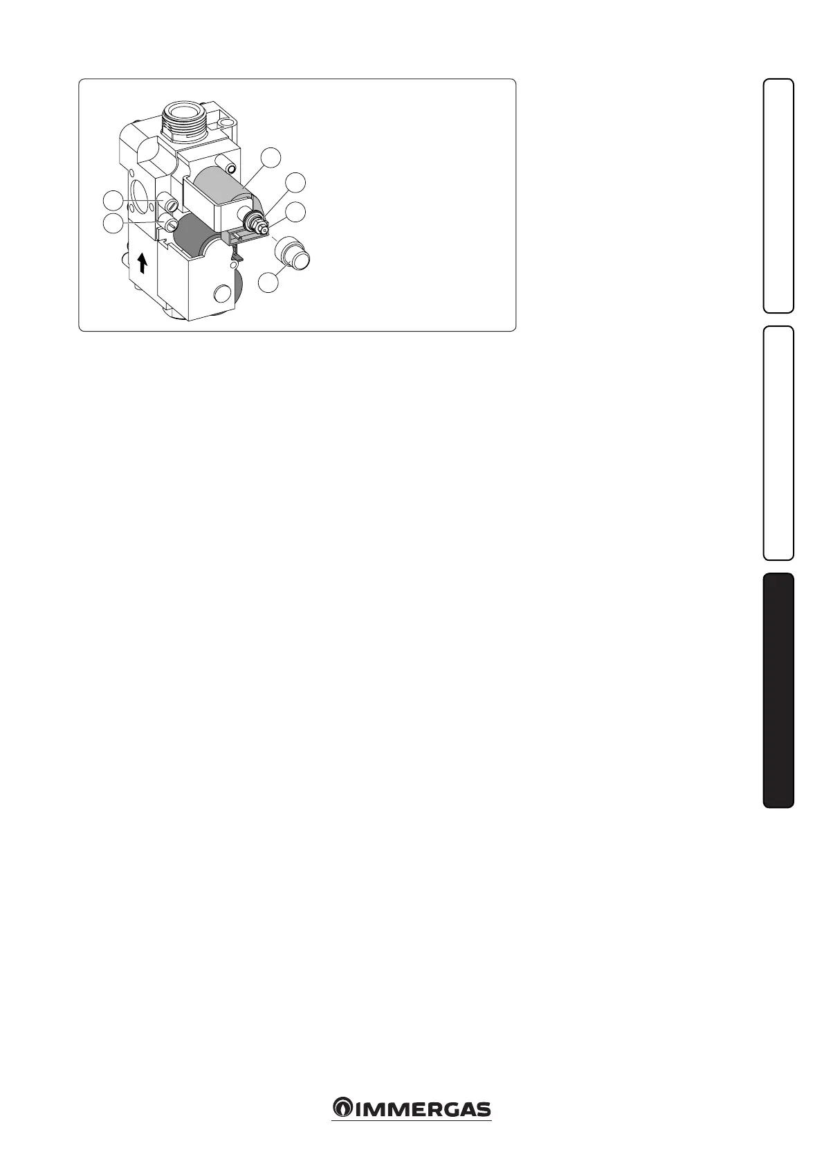
Key:
1 - Coil
2 - Minimum output adjustment
screws
3 - Maximum output adjust-
ment nut
4 - Outlet pressure point
gas valve
5 - Gas valve inlet pressure point
6 - Protection hood
VK 8105 M GAS valve