25
STVP ed 02/06 VICTRIX Plus
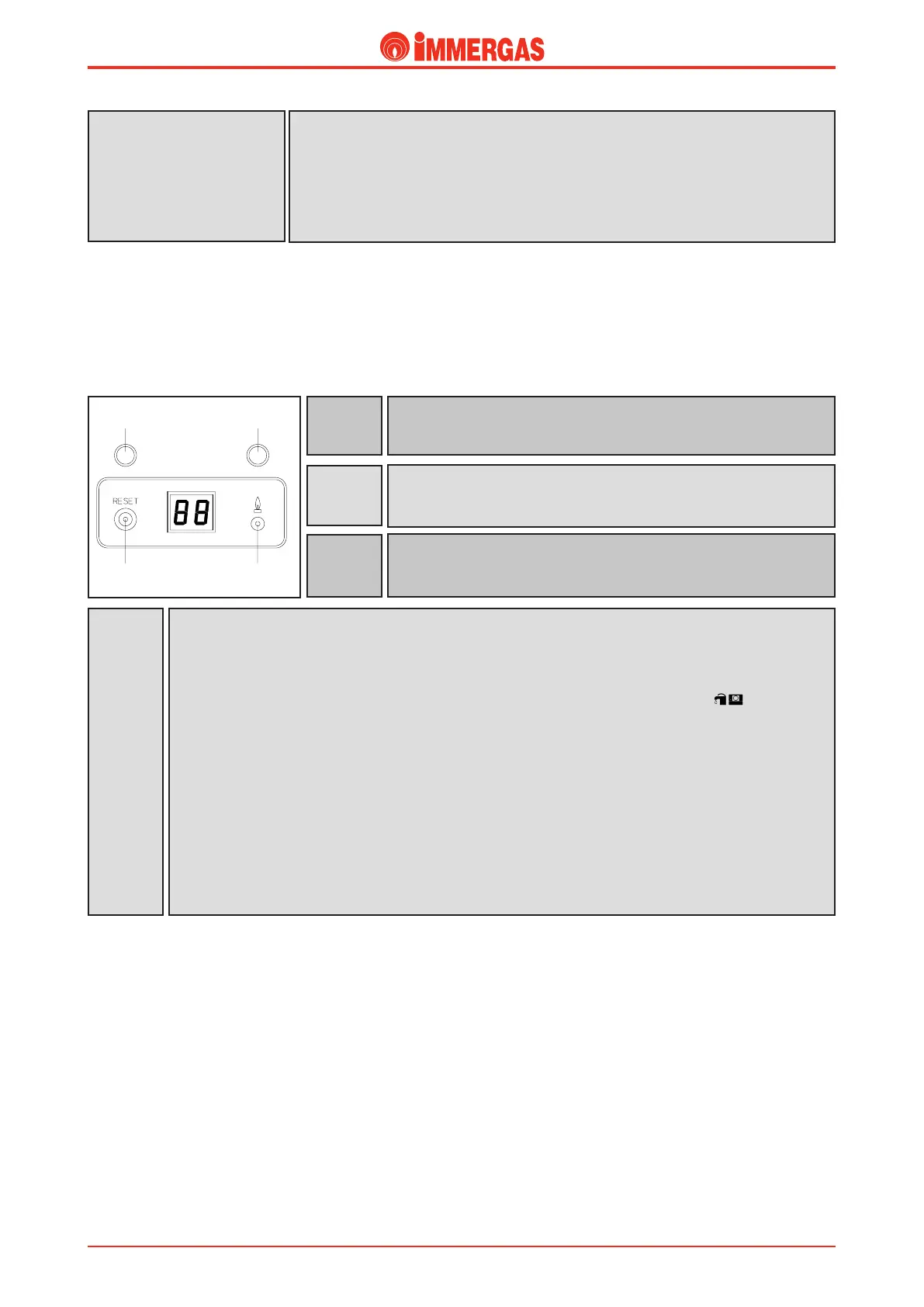
Indicators (display board).
DL1
Green LED that comes on when the boiler is working in the heating and
antifreeze modes.
Display
Depending on conditions, it indicates:
- e temperature read by the delivery sensor during operation in the heating, d.h.w., antifreeze and chim-
neysweep modes.
- e value set during heating and d.h.w. temperature adjustment (for a time of 5 seconds).
- e CE mark (external controls) with the CAR mounted and the main switch positioned on
- e code number relating to the safety device that has triggered:
01 = stop due to an ignition failure
02 = stop due to the overheating safety thermostat triggering / activation of fume thermostat
05 = breakage of the delivery NTC sensor
10 = no-water safety device
12 = breakage of the d.h.w. NTC sensor (storage tank)
14 = incorrect connection between the ignition control unit and board (control unit faulty)
16 = fan stop (fan faulty)
17 = incorrect fan speed
31 = incompatible remote control
DL2
Green LED that comes on when the boiler is working in the domestic
hot water mode.
DL3
Orange LED that comes on when the boiler is working.
DL1
DL2
DL3
PU1
If a fan speed outside safety limits is detected (700-5,700 rpm), the burner is switched off and
prevented from restarting for 7.5 minutes.
Triggering is indicated by error code 17 on the boiler panel display.
If the speed read drops to 500 rpm without the previous safety device triggering, the boiler switches
to “fan stop” and a manual reset is required with button PU1.
Triggering is indicated by error code 16 on the boiler panel display.
Fan speed safety device
Technical Documentation
Technical Documentation