3
STV50 ed 04/04 ermoregulation VICTRIX 50
Installation place.
a - Use without ambient probe.
If the ambient probe is not activated, the appliance can
be installed everywhere.
b - Use with ambient probe.
If the room thermostat is activated, the appliance must
be located at a height of 1,20-1,50 m and in a suitable
position for correctly measuring the temperature. For this
purpose an intermediate wall of the coldest zone can be
chosen.
e appliance must not be installed:
- in places directly exposed to sunlight.
- in the vicinity of appliances that produce heath such as TV
sets, refrigerators, wall lamps, radiators, etc.
- on walls behind which there are heating pipes or ues.
- on not insulated external walls.
- in corners or recesses, on shelves, or behind the curtains.
- near entrance doors of not heated rooms.
Installation.
After opening the upper part, the wall support can be xed in
the required place with the screws and plugs supplied.
e data bus cable must pass through the lower opening.
Recommended connection cable: J-Y(ST)Y 2 x 0.6
Max lenght: 50 m.
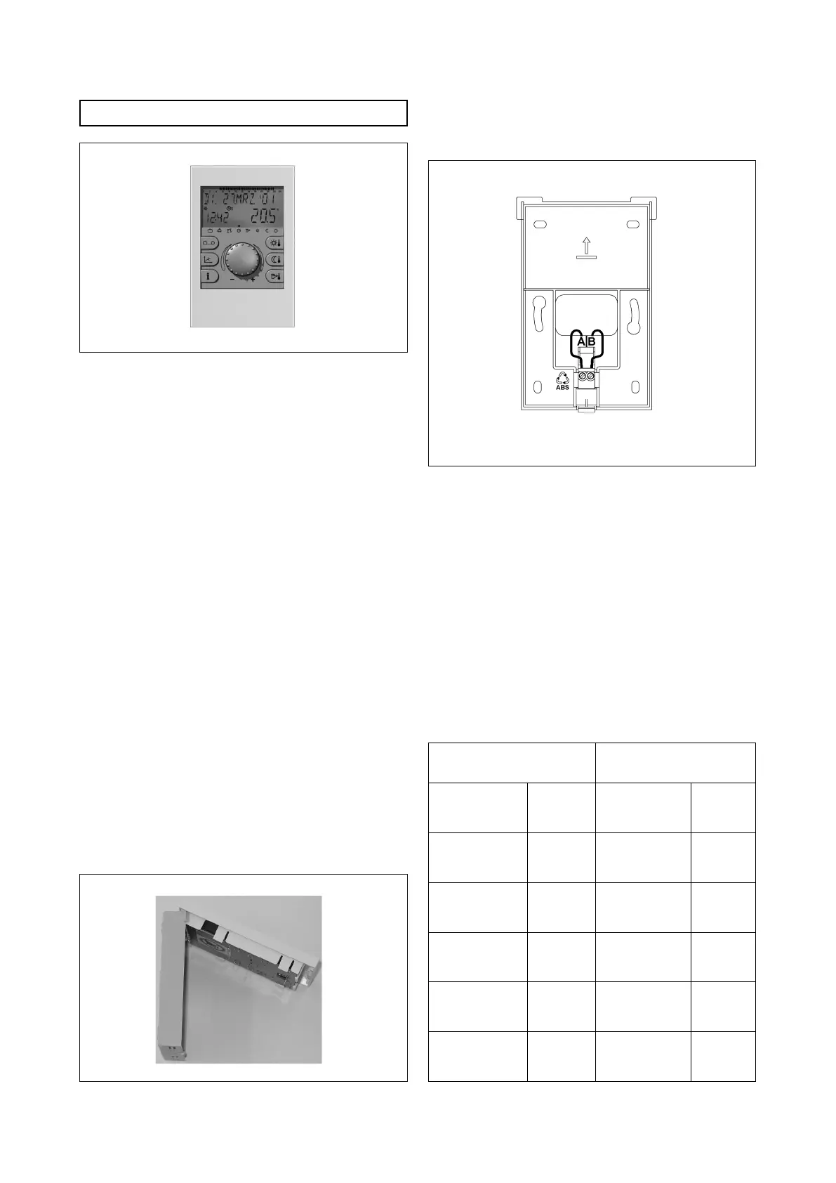
Pic. 5
Pic. 6
Electrical connection.
e two wired data bus cable must be connected to A and B
terminals .
Attention: respect the polarity when connecting the
data bus cable (A-B).
Wall support (without upper part)
Pic. 7
e connection must be executed respecting the polarity. e
display does not show anything whenever polarity is not res-
pected. After connecting electrically the zone manager, ret
the front cover till the clamping.
BUS address setting.
e connection between zones managers and cascade regulator
must be obtained through a data bus cable with two wires.
Since the zone managers are connected in parallel to the data
bus cable, the data transmission requires a bus address.
BUS address (zone manager).
e bus address classication between cascade regulators and
zone managers is dened by a rigid scheme set by the producer
as explained in the following scheme:
Cascade regulator Relative zone manager
Function
BUS
Address
Heating
circuit
BUS
Address
Main cascade
regulator
10
direct circuit
mixed circuit 1
mixed circuit 2
11
12
13
II°
cascade
regulator
20
direct circuit
mixed circuit 1
mixed circuit 2
21
22
23
III°
cascade
regulator
30
direct circuit
mixed circuit 1
mixed circuit 2
31
32
33
IV°
cascade
regulator
40
direct circuit
mixed circuit 1
mixed circuit 2
41
42
43
V°
cascade
regulator
50
direct circuit
mixed circuit 1
mixed circuit 2
51
52
53
Zones manager.