BUS address entry in the zone manager.
- First start-up.
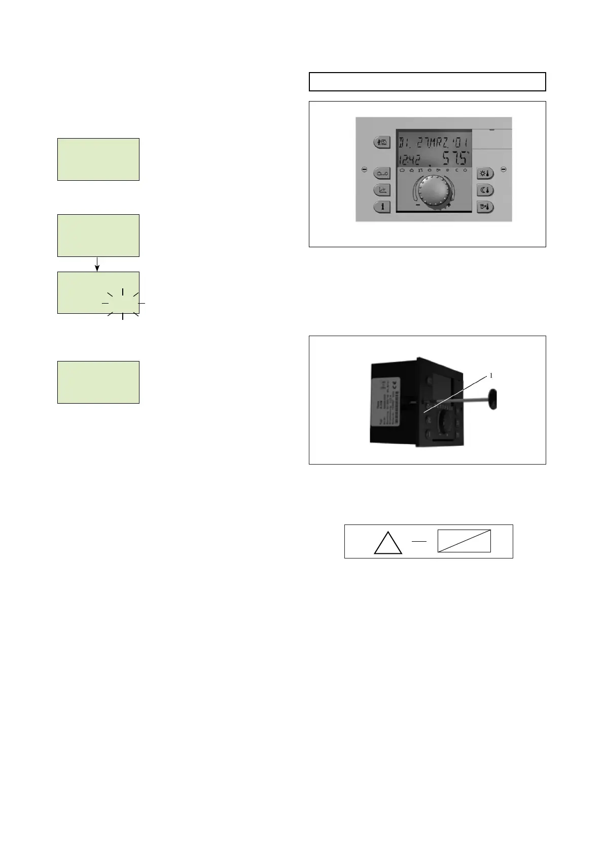
After completing the installation and starting up the system,
all available segments are visualized on the zone manager
display.
Segment test
Soon after the instrument identication and the bus address
are visualized.
Instrument identication
Type of instrument
Software date
Software version
Address input
see scheme above
After the bus address input and conrmation, pressing the
knob, automatically the associated heating circuit is visua-
lized:
Data bus address
Direct circuit
Main regulator
Attention:
Double input of the same data bus address causes data tran-
smission errors therefore wrong functioning of the thermo-
regulation.
- Bus address modication.
In order to modify the bus address, please follow the following
steps:
1 - Disconnect the data bus cable of the zone manager.
2 - Reconnect the zone manager keeping the knob pressed
until the bus address appears.
3 - Insert the new bus address and conrm.
00:00:0
000000000000
00:00
V 1.0
11:02
THETR RS
6 6 6 6 66 6 6
- 1 1
BUS address
ac --1
HC
data bus
Cascade and zones regulator installation.
e cascade regulator is designed for ush-mounted instal-
lation.
e xing is done turning clockwise the two lateral screws
(1).
Turn anti-clockwise for disassembling.
Electrical installation.
e electrical connection and wiring must be done in the
back side of the appliance as reported in the following page
scheme.
All the connection terminals inside the blue area (X1) work
with safety low voltage and they have not to connect to
the main supply voltage. If this happens the appliance will
destroy and you will lose the warranty!
e connection terminals inside the red area (X2….X4) work with
the main supply voltage.
Warning:
- For the wiring of the appliance the bus data and sensors
cables must be layed separately from electric wires. Sensor
and bus data cables cannot be layed together with electrical
supply wires of other electrical appliances.
- For the connection it is necessary to use the special connec-
tion terminals (X1÷X4) provided separately.
!
230 V ~
Pic. 8
Pic. 9
Cascade and zones regulator.