5
STV50 ed 04/04 ermoregulation VICTRIX 50
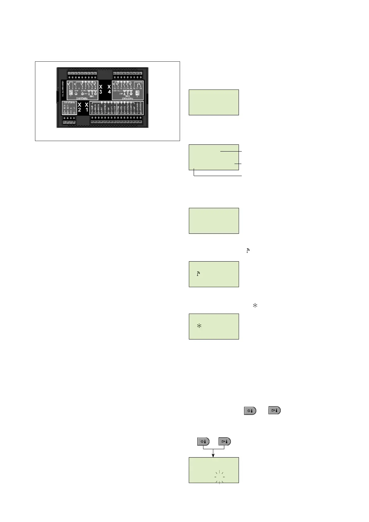
Cascade regulator electrical connection.
Main supply connection.
1 - Relay output (not used)
2 - Relay input (not used)
3 - Direct circuit pump (HC)
4 - N.C.
5 - Domestic hot water circuit pump
6 - L 1/ 230 V (main supply)
7 - Mixed circuit valve (MC 1) OPEN
8 - Mixed circuit valve (MC 1) CLOSED
9 - Mixed circuit 1 pump
10 - Variable output relay 1
11 - Variable output relay 2
12 - L 1 230/V
13 - Mixed circuit valve (MC 2) OPEN
14 - Mixed circuit valve (MC 2) CLOSED
15 -
Mixed circuit 2 pump
16 - N.C.
17 - Relay output (not used)
18 - Relay input (not used)
19 - (not used)
20 - (not used)
21 - N/230V
22 - L1 /230V
Low tension connections.
23 - GND common
24 - Data bus connection - signal A (zone controls and room thermostats)
25 - Data bus connection - signal B (zone controls and room thermostats)
26 - External sensor (not to use, connect to the boiler)
27 - (not to use)
28 - Domestic hot water sensor
29 - Temperature sensor zone 1
30 - Variable input 1
31 - Variable input 2
32 - Variable input 3
33 - Temperature sensor zone 2
34 - (not to use)
35 - (not to use)
36 - Impulses input
37 - Boiler data bus A
38 - Boiler data bus B
NOTE: For the connection to the hydraulic circuit components see the schemes
at pages 8-11.
Bus address (Cascade regulator).
In case that only one cascade regulator is installed, the bus
address is always 10. With more regulators connected (at least
ve) the regulator directly connected to the boiler must have
the bus address 10. For the other regulators, the addresses must
follow numbers 20, 30, 40 e 50.
}
main supply
Pic. 10
Zones and cascade regulator start up.
Segment test and instrument identication.
At the rst appliance start up or when power supply is restored
all the display segments are visualized:
Segment test
e instrument model with its type code and software version
is then displayed.
Type of instrument
software version
type code
If no errors are signalled, the standard display appears indica-
ting date, time and current boiler temperature.
Standard display
Wednesday 21 August 2001
time 16:32 Temperature 63,5°C
e active summer switching-o appears on the standard display
with a sunshade symbol (
).
Summer switching-o
active
e active anti-freeze function appears on the standard display
with a snow crystal symbol (
).
Anti-freeze protection
active
Code entering for parameters modication.
Technician code.
After entering the code, the parameters reserved for the tech-
nician are activated: these ones can be modied according to
the characteristics of the system.
Code entering.
For entering the technician code it's necessary to press at the
same time the buttons
and for approx. 3 seconds
until the word "code" appears on the display.
000000000000
00:00
6 6 6 6 66 6 6
00:00:0
V 1.0
15
U 223BVV
+
63.5°
16:32
WE 21.AUG. ‘01
6
63.5°
16:32
WE 21.AUG. ‘01
6
63.5°
16:32
WE 21.AUG ‘01
6
0 0 0 0
C O D E
 Loading...


