VICTRIX PRO V2 EU
110
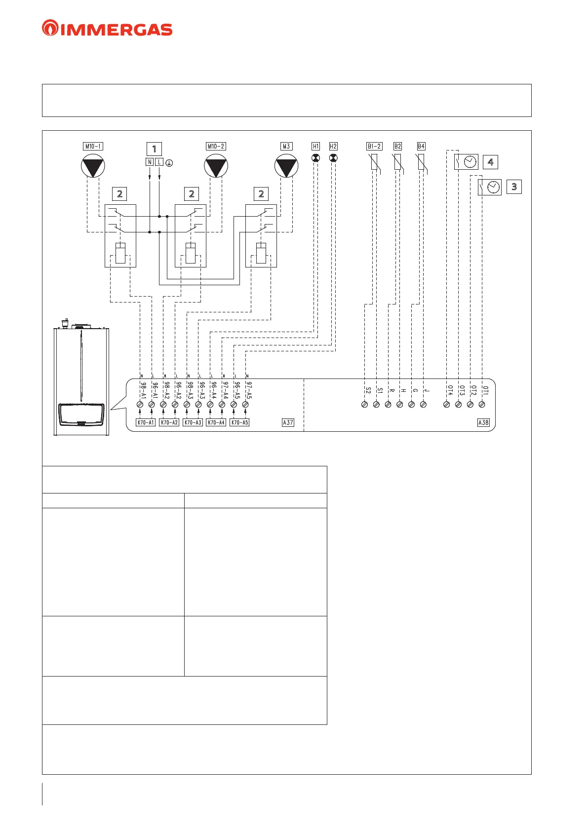
26.15 WIRING DIAGRAM: DHW ZONE HYDRAULIC SEPARATOR
2 DIRECT ZONES WITH CH DEMAND WITH EXTERNAL PROBE
Key:
A37 - Connection sheet (loads)
A38 - Connection card (signals)
B1-2 - System ow probe (NTC) (optional)
B2 - Domestic hot water probe (NTC)
(optional)
B4 - External probe (NTC) (optional)
H1 - "ERROR" indicator light
(230 Vac) (optional)
H2 - “Burner on” indicator light
(230 Vac) (optional)
M3 - DHW pump (optional)
M10-1 - Zone 1 circulator pump (optional)
M10-2 - Zone 2 circulator pump (optional)
1 - 230 Vac - 50 Hz
2 - External relay (optional)
230 vAC coil Max 0,1 A
3 - Programming clock Zone 1
(optional)
4 - Programming clock Zone 2
(optional)
“HYDRAULIC SETTINGS”
parameter conguration table (Technician menu)
Parameter/menu name Setting
“Relay settings” submenu:
- K70-A1
- K70-A2
- K70-A3
- K70-A4
- K70-A5
- K70-A6
- K70-A7
System pump conguration
- Zone 1 pump
- Zone 2 pump
- Domestic hot water pump
- Error
- Burner on
- Relay not used
- Relay not used
- Not used
- System sensor
- Type of heating request
- DHW request type
- Parallel mode
- Heating + domestic hot water mode
- External temperature climatic curve
- Sensor
- Disabled
Note: when the contact of the programmer clock is closed, the heating setpoint is
reduced according to the parameter "Reduction of ECO heating setpoint zone 1
and "Reduction of ECO heating setpoint zone 2". As an alternative to the
programming clock, use the schedule)
1
2
3
4
2 2
 Loading...