VICTRIX PRO V2 EU
111
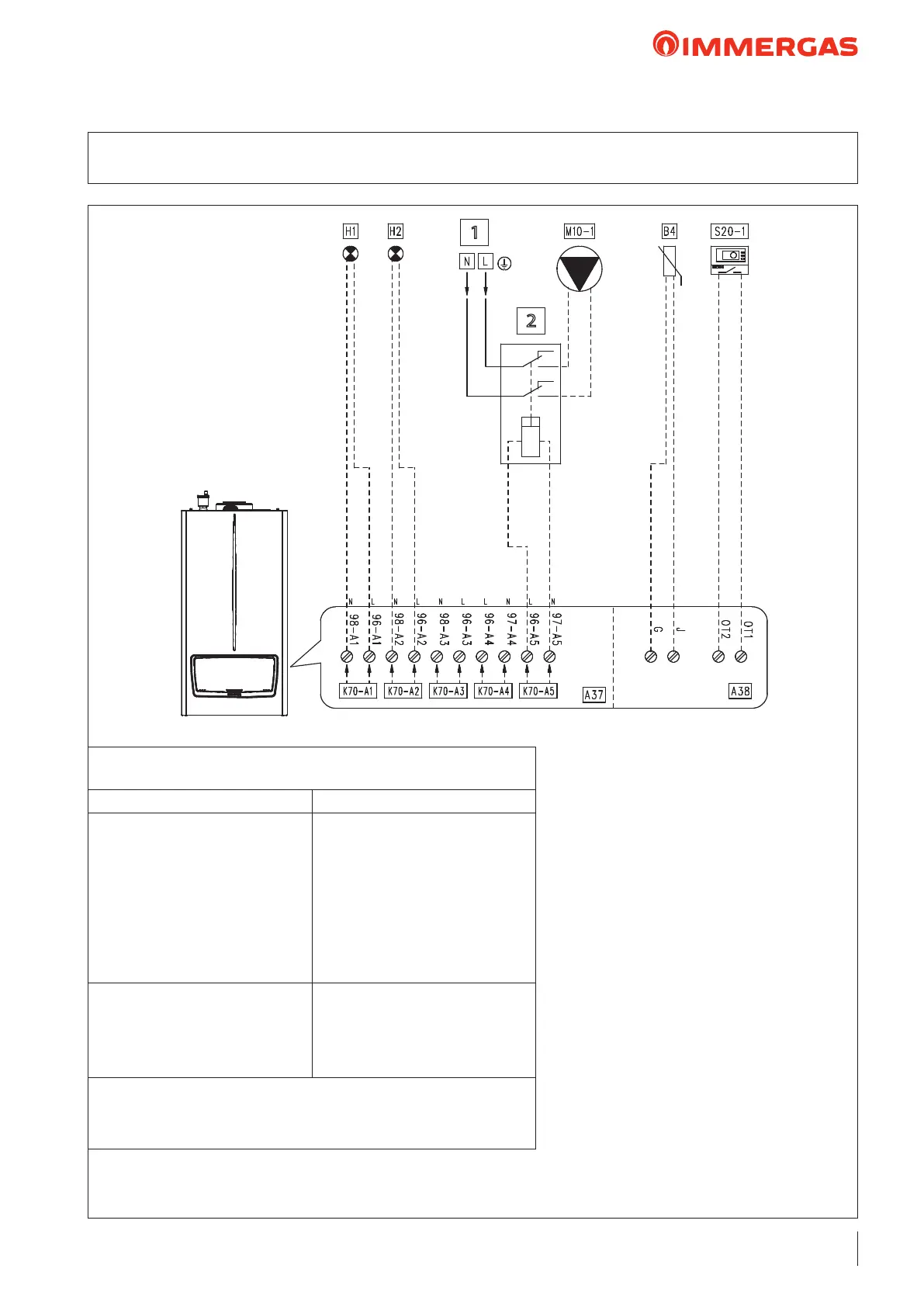
26.16 WIRING DIAGRAM:
DIRECT ZONE 1 WITH THE BOOSTER PUMP
Key:
A37 - Connection sheet (loads)
A38 - Connection card (signals)
B4 - External probe (NTC) (optional)
H1 - "ERROR" indicator light
(230 Vac) (optional)
H2 - "Burner on" indicator light
(230 Vac) (optional)
M10-1 - Zone 1 circulator pump (optional)
S20-1 - Zone 1 room thermostat (optional)
S50 - DHW ermostat/Contact
1 - 230 Vac - 50 Hz
2 - External relay (optional)
230 vAC coil Max 0,1 A
“HYDRAULIC SETTINGS”
parameter conguration table (Technician menu)
Parameter/menu name Setting
“Relay settings” submenu:
- K70-A1
- K70-A2
- K70-A3
- K70-A4
- K70-A5
- K70-A6
- K70-A7
System pump conguration
- Error
- Burner on
- Relay not used
- Relay not used
- Booster pump
- Relay not used
- Relay not used
- Not used
- System sensor
- Type of heating request
- DHW request type
- Parallel mode
- Not used
- Climatic curve outside temperature
and room thermostat
- Sensor
- Disabled
Note: e booster pump is activated together with the appliance’s pump though
not simultaneously
1
2
 Loading...