VICTRIX PRO V2 EU
141
NOTE: e diagram provided here is indicative, see notes on the back of the cover
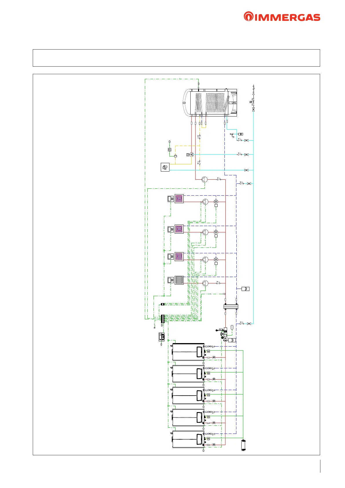
38 HYDRAULIC DIAGRAM: VICTRIX PRO V2 EU IN SET CONFIGURATION WITH CASCADE
AND ZONE REGULATOR + EXPANSION WITH 1 DIRECT ZONE 3 MIXED ZONES AND 1 DHW ZONE
M3
B1
2
2
HMIX
C
V
2 2
230Vac
M4
M10-1 M10-3
M
M31-3
B3-3
2
2
3
2
2
2BUS
B2
AC
MU
RU
MP
RP
AF
RC
B2
UB
2BUS
A40
V
B4
2
INAIL
V
3
230 Vac
R
SC
G
V
M
C
NC
3
3
R
SC
G
V
M
C
MZ1
RZ1
MZ1
RZ1
SP
2BUS
R
SC
G
V
M
C
R
SC
G
V
M
C
R
SC
G
V
M
C
2BUS2BUS
M10-2
M
M31-2
B3-2
2
2
3
A41-1 A41-2 A41-3
2BUS
2BUS
M10-4
M
M31-4
B3-4
2
2
3
A41-4
2BUS
A42
A40
2BUS
V
2BUS
LEGENDA:
A40 Regolatore di cascata e zone VICTRIX PRO V2
A41-1 Gestore di zona 1
A41-2 Gestore di zona 2
A41-3 Gestore di zona 3
A41-4 Gestore di zona 4
A42 Espansione per Regolatore di cascata e zone VICTRIX PRO V2
B1 Sonda mandata comune
B2 Sonda bollitore
B3-2 Sonda mandata impianto zona 2
B3-3 Sonda mandata impianto zona 3
B3-4 Sonda mandata impianto zona 4
B4 Sonda esterna
M3 Circolatore sanitario
M4 Circolatore di ricircolo sanitario
M10-1 Circolatore di rilancio zona 1
M10-2 Circolatore di rilancio zona 2
M10-3 Circolatore di rilancio zona 3
M10-4 Circolatore di rilancio zona 4
M31-2 Valvola miscelatrice zona 2
M31-3 Valvola miscelatrice zona 3
M31-4 Valvola miscelatrice zona 4
C Caldaia VICTRIX PRO 100-120-150 V2
NC Neutralizzatore di condensa
SP Scambiatore a piastre
UB Unità bollitore
NOTE:
si ricorda di realizzare i circuiti di scarico condensa
il presente schema funzionale è esemplificativo
verificare i libretti istruzioni per la predisposizione degli allacciamenti idraulici ed elettrici
e per la sezione dei cavi
verificare i libretti istruzioni per il posizionamento dei componenti e delle distanze
massime ammissibili
In presenza di Regolatore di Cascata e Zone è necessario prevedere 1 Clip-In 3.034122
per ogni caldaia VICTRIX PRO V2
Il Regolatore di Cascata e Zone A40: composto da interfaccia utente
e da morsettiera (da installare su guida DIN)
è possibile prevedere fino a 2 espansioni A42 per ogni Regolatore di Cascata e Zone
›
›
›
›
›
›
›
caldaia VICTRIX PRO V2 EU
C Caldaia VICTRIX PRO V2 EU
KEY:
NOTES:
> remember to install the condensate drain circuits
> this diagram is an example
> check the instruction booklets for the set up of the hydraulic and electric connections and for the
cross-section of the cables
> check the instruction booklets for positioning of the components and maximum allowable distances
> In the presence of a Cascade and zone regulator, 1 clip-In 3.034122 must be provided for each
VICTRIX PRO V2 EU boiler
> The Cascade and zone regulator A40 : consists of user interface and terminal board (to be
installed on DIN rail)
> Up to 2 expansions A42 can be provided for each Cascade and zone regulator
VICTRIX PRO V2 cascade and zone regulator
Zone 1 manager
Zone 2 manager
Zone 3 manager
Zone 4 manager
Expansion for Cascade and zone regulator
Common ow probe
Storage tank probe
System ow probe zone 2
System ow probe zone 3
System ow probe zone 4
External probe
DHW pump
Domestic hot water recirculation pump
Zone 1 booster pump
Zone 2 booster pump
Zone 3 booster pump
Zone 4 booster pump
Zone 2 mixing valve
Zone 3 mixing valve
Zone 4 mixing valve
VICTRIX PRO V2 EU boiler
Condensate neutraliser
Plate heat exchanger
Storage tank unit
 Loading...