VICTRIX PRO V2 EU
142
NOTE: e diagram provided here is indicative, see notes on the back of the cover
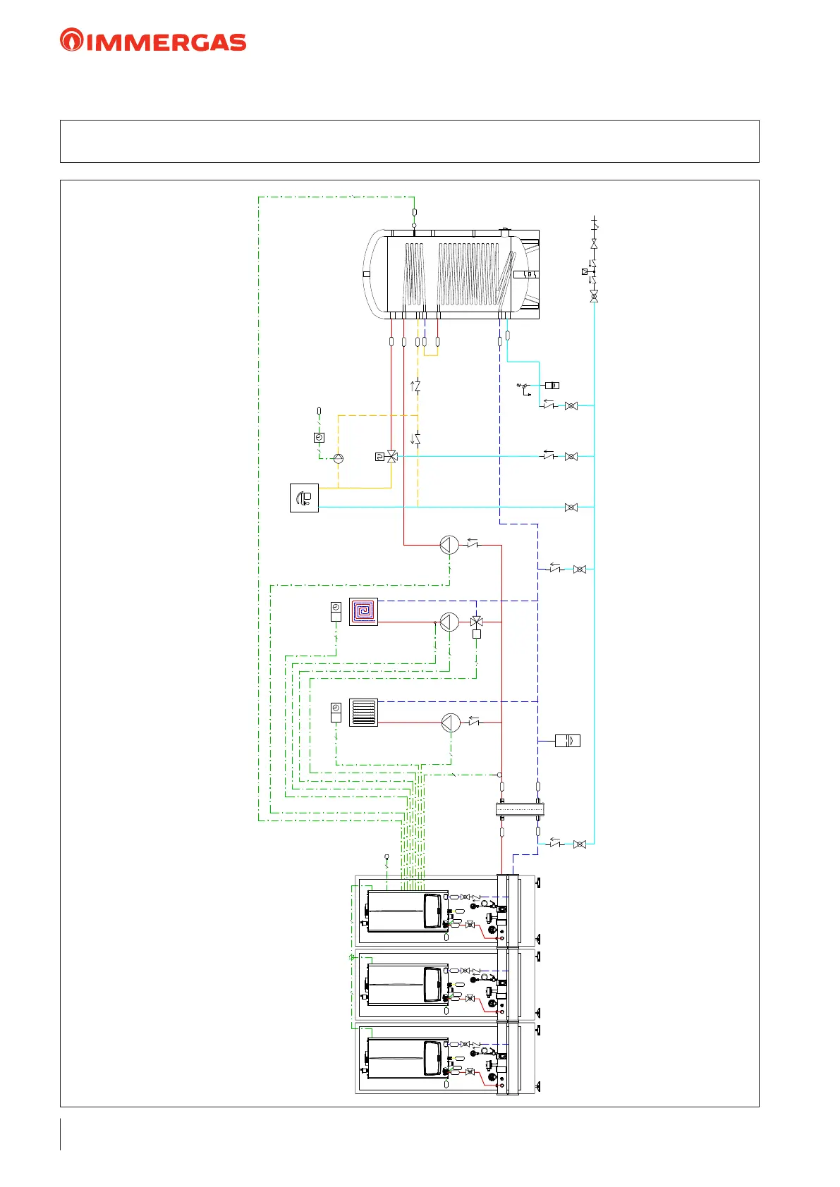
39 HYDRAULIC DIAGRAM: 3 VICTRIX PRO V2 EU WITH CABINET IN SIMPLE
CASCADE WITH 1 DIRECT ZONE 1 MIXED ZONE AND 1 DHW ZONE
M3
B4
2
B1
2
2
HMIX
C
V
2 2
230Vac
M4
M10-1
M10-2
M
M31-2
B3-2
2
2
3
2
2
T
S20-2
2
T
S20-1
2
B2
AC
MU
RU
MP
RP
AF
RC
B2
UB
3 3
MZ1
RZ1
MZ1
RZ1
SP
G
R
M
SC
V
C
G
R
M
SC
V
C
G
R
M
SC
V
C
LEGENDA:
B1 Sonda mandata comune
B2 Sonda bollitore
B3-2 Sonda mandata impianto zona 2
B4 Sonda esterna
M3 Circolatore sanitario
M4 Circolatore di ricircolo sanitario
M10-1 Circolatore di rilancio zona 1
M10-2 Circolatore di rilancio zona 2
M31-2 Valvola miscelatrice zona 2
S20-1 Cronotermostato ambiente zona 1
S20-2 Cronotermostato ambiente zona 2
C Caldaia VICTRIX PRO 35-55-80 V2 in armadio con collettore e sicurezze INAIL
SP Scambiatore a piastre
UB Unità bollitore
NOTE:
si ricorda di realizzare i circuiti di scarico condensa
il presente schema funzionale è esemplificativo
verificare i libretti istruzioni per la predisposizione degli allacciamenti idraulici ed elettrici
e per la sezione dei cavi
verificare i libretti istruzioni per il posizionamento dei componenti e delle distanze
massime ammissibili
per la termoregolazione è possibile utilizzare termostati a contatti puliti o dotati di
protocollo di comunicazione OPENTHERM
›
›
›
›
›
C Caldaia VICTRIX PRO V2 EU in armadio con collettore e sicurezze
Common ow probe
Storage tank probe
System ow probe zone 2
External probe
DHW pump
Domestic hot water recirculation pump
Zone 1 booster pump
Zone 2 booster pump
Zone 2 mixing valve
Zone 1 room chrono-thermostat
Zone 2 room chrono-thermostat
VICTRIX PRO V2 EU boiler in cabinet with manifold and safety devices
Plate heat exchanger
Storage tank unit
KEY:
NOTES:
> remember to install the condensate drain circuits this functional diagram is an example
> check the instruction booklets for the set up of the hydraulic and electric connections and for the
cross-section of the cables
> check the instruction booklets for positioning of the components and maximum allowable distances
> for temperature control, potential-free contact thermostats or ones provided with OPENTHERM
communication protocol can be used
 Loading...