VICTRIX PRO V2 100 - 120 - 150 EU
16
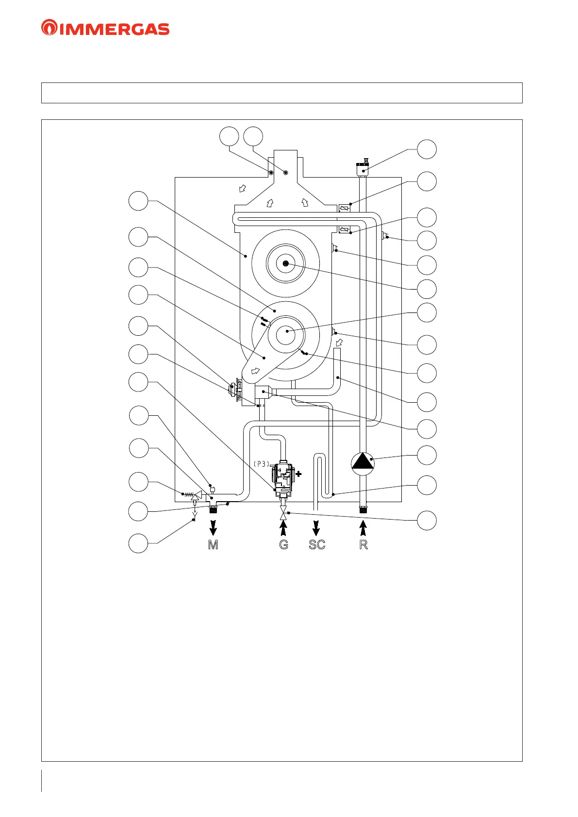
5.1 VICTRIX PRO V2 100 120 150 EU HYDRAULIC DIAGRAM
1
2
3
4
5
6
7
8
9
10
11
12
13 14
15
16
17
18
19
20
21
22
23
24
25
26
27
28
KEY:
1 - Draining funnel on view
2 - Boiler draining cock
3 - 5.4 bar safety valve
4 - Flow manifold
5 - Pressure transducer
6 - Gas valve
7 - Gas nozzle
8 - Air fan
9 - Manifold cover
10 - Ignition electrode
11 - Condensation module cover
12 - Condensation module
13 - Air sample point
14 - Flue sample point
15 - Condensation module air vent valve
16 - System ow regulation probe
17 - System return regulation probe
18 - Overheating safety thermostat
19 - Safety thermostat (manual reset)
20 - Flue probe with thermofuse
21 - Burner
22 - Heat exchanger safety thermofuse
23 - Ignition electrode
24 - Air intake pipe
25 - Venturi
26 - Pump
27 - Condensate trap siphon
28 - Gas cock
M - System ow
SC - Condensate drain
G - Gas supply
R - System return