VICTRIX PRO V2 EU
26
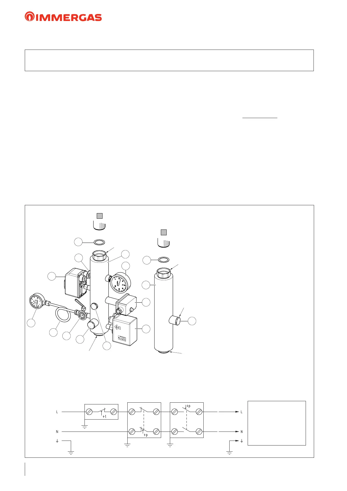
e safety device kit is INAIL-approved for vertical installa-
tion directly under the boiler, placing the relative gaskets in
between. With outdoor installation it needs to be protected
using the IPX4D protection box kit for INAIL single boiler
safety devices, code 3.024028, or nonetheless protected from
the elements based on its electrical protection rating.
Immergas S.p.a. declines all liability whenever the installer does
not use the devices and INAIL-approved Immergas original kits
or uses them improperly.
e sensitive elements of the INAIL safety devices must be set
up as described in the installation instructions, in compliance
with the provisions set forth in the ''R'' collection.
Regarding INAIL design, when installing the Immergas safety
kits, the following INAIL approved devices are already present:
- Pressure gauge-holder cock;
- Pressure gauge;
- ermometer;
- Manual reset thermostat;
- Maximum pressure switch and minimum pressure switch,
both with manual reset;
the boiler is already equipped as per standard with a draining
funnel with 4 bar Safety valve for VICTRIX PRO V2 35 - 55
- 60 - 68 - 80 EU boilers and 5,4 bar for VICTRIX PRO V2
100 - 120 - 150 and 180 EU boilers.
ere is a tting for an expansion vessel on the ow and return
stub pipes.
KEY:
1 - Gasket 44 x 34 x 2
2 - ermometer pocket
3 - Brass plug G1/2" (possibly with F.S.O.V. t-
ting)
4 - INAIL type-approved pressure gauge-holder
cock
5 - INAIL-approved thermometer (scale 0-120
°C)
6 - INAIL-approved manual reset thermostat
(calibration temperature of 95 °C)
7 - INAIL-approved manual reset pressure switch
(1-5 bar adjustment - 3 bar factory setting)
10 - G 3/4" brass plug
11 - Damper coil
12 - INAIL type-approved pressure gauge
(scale 0-10 bar)
13 - INAIL-approved minimum pressure switch
(0.5-1.7 bar adjustment - 0.9 bar factory set-
ting)
14 - Insulated ow stub pipe
L = 350 mm
15 - Insulated return stub pipe L=350 mm
M - System ow
R - System return
Safety ther-
mostat
Electrical connection diagram for INAIL safety device kit
Safety pres-
sure switch
Minimum pressure
switch
M
R
6
15
1
G1"1/2
G3/4"
10
G1"1/2
7
G1"1/2
3
10
4
11
12
13
2
1
5
14
G1"1/2
9 INAIL SAFETY DEVICES KIT FOR SINGLE BOILER
VICTRIX PRO V2 EU
To the supply
Single or set boiler
conguration
230 Vac
50 Hz
MAINS