VICTRIX PRO V2 EU
96
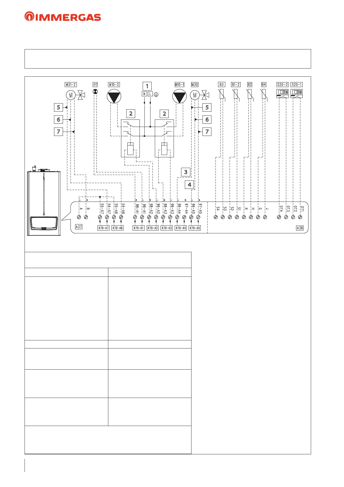
26.1 WIRING DIAGRAM: 3WAY DHW VALVE HYDRAULIC SEPARATOR
DIRECT ZONE 1 MIXED ZONE 2
1
2
3
4
5
6
7
2
5
6
7
“HYDRAULIC SETTINGS”
parameter conguration table (Technician menu)
Parameter/menu name Setting
“Relay settings” submenu:
- K70-A1
- K70-A2
- K70-A3
- K70-A4
- K70-A5
- K70-A6
- K70-A7
System pump conguration
- Error
- Zone 2 pump
- Zone 1 pump
- 3-way valve DHW
- 3-way valve CH
- Mixing valve: opens
- Mixing valve: closes
- Not used
- System sensor - C.H. mode
“Mixed zone" submenu:
- Mixed zone selection
- Valve time
- 2
- 150
- Type of heating request
- DHW request type
- Parallel mode
- Climatic curve outside temperature
and room thermostat
- Sensor
- Disabled
"3-way valve" submenu:
- 3-way valve selection
- 3-way valve stroke time
- Default position
- Motorised
- 12
- Central heating
Note: If you want to use zone 1 as a mixed zone and zone 2 as a direct zone, you
have to set the “Select mixed zone" parameter to "1", and then set the setpoints of
zone 1 and zone 2 correctly.
Key:
A37 - Connection sheet (loads)
A38 - Connection card (signals)
B1-2 - System ow probe (NTC)
(optional)
B2 - Domestic hot water probe (NTC)
(optional)
B3 - Flow probe (Low temperature)
(NTC) (optional)
B4 - External probe (NTC) (optional)
H1 - "ERROR" indicator light
(230 Vac) (optional)
M10-1 - Zone 1 circulator pump (optional)
M10-2 - Zone 2 circulator pump (optional)
M30 - 3-way valve (optional)
M31-2 - Mixing valve - zone 2 (optional)
S20-1 - Zone 1 room thermostat (optional)
S20-2 - Zone 2 room thermostat (optional)
1 - 230 Vac - 50 Hz
2 - External relay (optional)
230 vAC coil Max 0,1 A
3 - Domestic hot water
4 - Central heating
5 - Close
6 - Open
7 - Common
 Loading...