34
INSTALLERUSERMAINTENANCE TECHNICIANTECHNICAL DATA
C
53
* - C
83
1
4
7
9
5
5
6
7
8
3
2
S
A
27
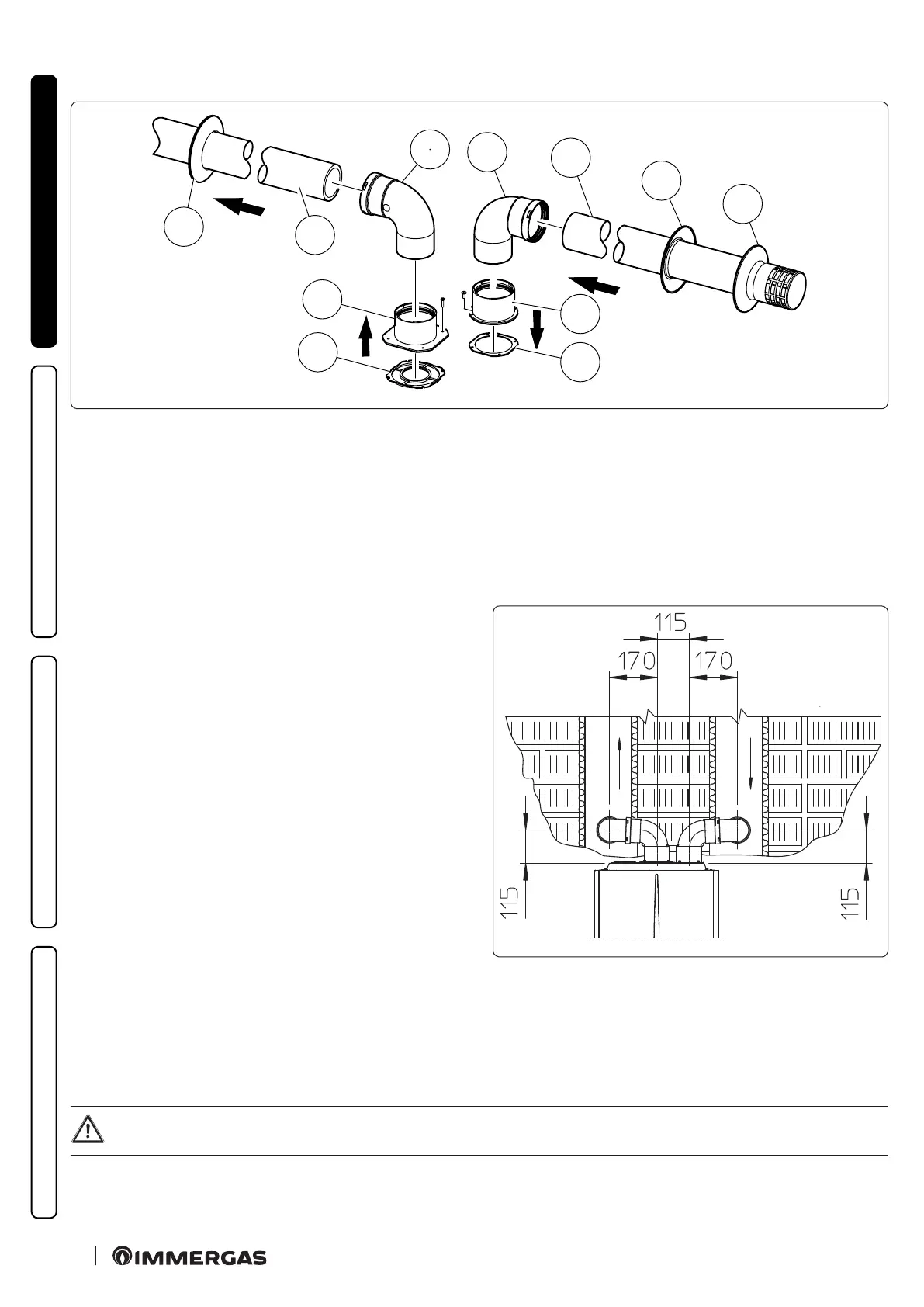
e kit includes (Fig. 27):
N°1 Exhaust gasket (1)
N°1 Flange gasket (2)
N°1 Female intake ange (3)
N°1 Female exhaust ange (4)
N°2 Ø 80 90° bend (5)
N°1 Intake terminal Ø 80 (6)
N°2 Internal wall sealing plates (7)
N°1 External wall sealing plate (8)
N°1 Exhaust pipe Ø 80 (9)
* to complete C53 conguration, also provide for a “green range” roof
discharge terminal. e conguration on walls opposite the build-
ing is not allowed.
Installation clearances (Fig. 28)
e minimum installation clearance measurements of the Ø
80/80 separator terminal kit have been stated in some limit condi-
tions.
C
43
28
Extensions for separator kit Ø 80/80
e maximum vertical straight length (without bends) that can be used for Ø 80 intake and exhaust pipes is 41 metres, regardless from
whether they are used for intake or exhaust.
e maximum horizontal straight length (with bend in suction and in exhaust) that can be used for Ø 80 intake and exhaust pipes is 36
metres, regardless from whether they are used for intake or exhaust.
Please note the type of installation C
43
must be done with a natural draught ue.
To aid in the removal of possible condensate forming in the exhaust pipe, tilt the pipes towards the appliance with a minimum
slope of 1.5% (Fig. 29)





 To Next Page