C12
1-18
C12
1-19
C32
1-211-20
C32
1
2
6
4
3
5
6
2
1
3
4
5
7
8
*
*
10 - IE
INSTALLATORUSERMAINTENANCE
Max 12200 mm
Max 4700 mm
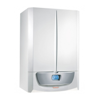
e kit includes:
N°1 - Seal (1)
N°1 - Concentric bend Ø 60/100 (2)
N°1 - Adapter Ø 60/100 for Ø 80/125 (3)
N°1 - Concentric intake/exhaust
terminal Ø 80/125
N°1 - Internal ring (5)
N°1 - External ring (6)
• Coupling extension pipes and concentric el-
bows. To install possible coupling extensions
on other fume extraction elements, proceed
as follows: t the male end (smooth) of the
concentric pipe or concentric elbow up to the
stop on the female end (with lip seals) of the
previously installed element; this will ensure
correct hold and joining of the elements.
Caution: if the exhaust terminal and/or exten-
sion concentric pipe needs shortening, consider
that the internal duct must always protrude by 5
mm with respect to the external duct.
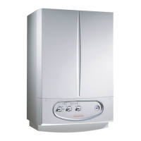
is specic terminal enables ue exhaust and
air intake in a vertical direction.
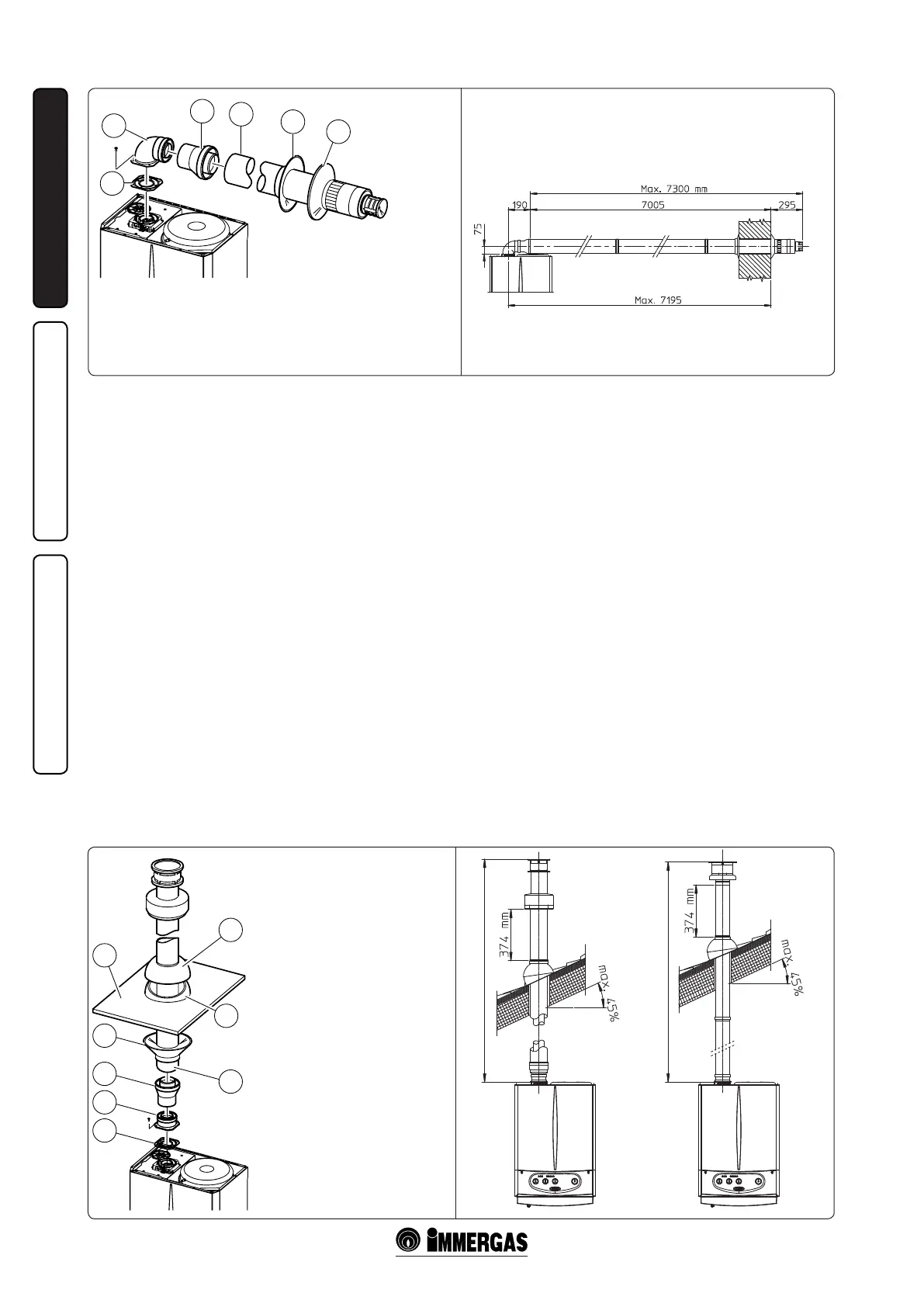
N.B.: the vertical kit Ø 80/125 with aluminium
tile enables installation on terraces and roofs with
maximum slope of 45% (24°). e height between
the terminal cap and half-shell (374 mm) must
always be respected.
e vertical kit with this conguration can be
extended up to a maximum of 12200 mm vertical
rectilinear, including the terminal (Fig. 1-21).
is conguration correspondsto a resistance
factor of 100. In this case specic extensions
must be requested.
The terminal Ø 60/100 can also be used for
vertical exhaust, in conjunction with concentric
ange code no. 3.011141 (sold separately). e
e kit includes:
N°1 - Seal (1)
N°1 - Female concentric ange (2)
N°1 - Adapter Ø 60/100 for Ø 80/125 (3)
N°1 - Ring (4)
N°1 - Aluminium tile (5)
N°1 - Intake/Exhaust concentric pipe
Ø 80/125 (6)
N°1 - Fixed semi-shell (7)
N°1 - Mobile half-shell (8)
height between the terminal cap and half-shell
(374 mm) must always be respected (Fig. 1-21).
e vertical kit with this conguration can be
extended to a max. straight vertical length of 4700
mm, including the terminal (Fig. 1-21).
Separator kit Ø 80/80. e separator kit Ø 80/80,
enables separation of the exhaust ues and air
intake pipes according to the diagram shown in
the gure. (Fig. 1-22). Fumes are expelled from
duct (S). Air is taken in through duct (A) for
combustion. Intake duct (A) can be installed
either on the right or le hand side of the central
exhaust duct (S). Both ducts can be routed in
any direction.
• Assembly of separator kit Ø 80/80. Install the
ange (4) on the central hole of the boiler
inserting the seal (1) and tighten using the
hex and flathead screws supplied with the
kit. Remove the at ange in the lateral hole
with respect to the central one (depending on
installation requirements) and replace with
ange (3) inserting the seal (2) already tted
on the boiler and tighten using the self-tapping
screws supplied. Fit the male end (smooth) of
the bends (5) in the female end of the anges (3
and 4). Fit the male end (smooth) of the intake
terminal (6) up to the stop on the female end
of the bend (5), making sure that the relevant
internal and external rings are tted. Join the
exhaust pipe (9) with the male section (smooth)
in the female section of the bend (5) to the end
stop, ensuring that the internal washer is tted;
this will ensure the sealing eciency of the kit
components.
• Snap t extension pipe ttings and elbows. To
install snap-t extensions with other elements
of the fume extraction elements assembly,
proceed as follows: t the pipe or elbow with
the male section (smooth) in the female section
(with lip seal) to the end stop on the previously
installed element; in this way sealing eciency
of the couplings is assured.
• e gure (Fig. 1-24) shows the conguration
with vertical exhaust and horizontal intake.
• Installation clearances. e gure (Fig. 1-23)
gives the min. installation space dimensions
of the Ø 80/80 separator terminal kit al limit
condition.
• Extensions for separator kit Ø 80/80. e max.
vertical straight length (without bends) usable
for Ø 80 intake and exhaust pipes is 41 metres
of which 40 intake and 1 exhaust. is total
length corresponds to a resistance factor of 100.
e total usable length, obtained by adding the
length of the intake and exhaust pipes Ø 80,
must not exceed the maximum values given
in the following table. If mixed accessories or
components (are used (e.g. changing from a