6
5
1
3
2
7
8
5
9
7
4
S
A
C82
1-22
C42
C52
1-23
1-25
C82
1-24
11 - IE
INSTALLATORUSERMAINTENANCE
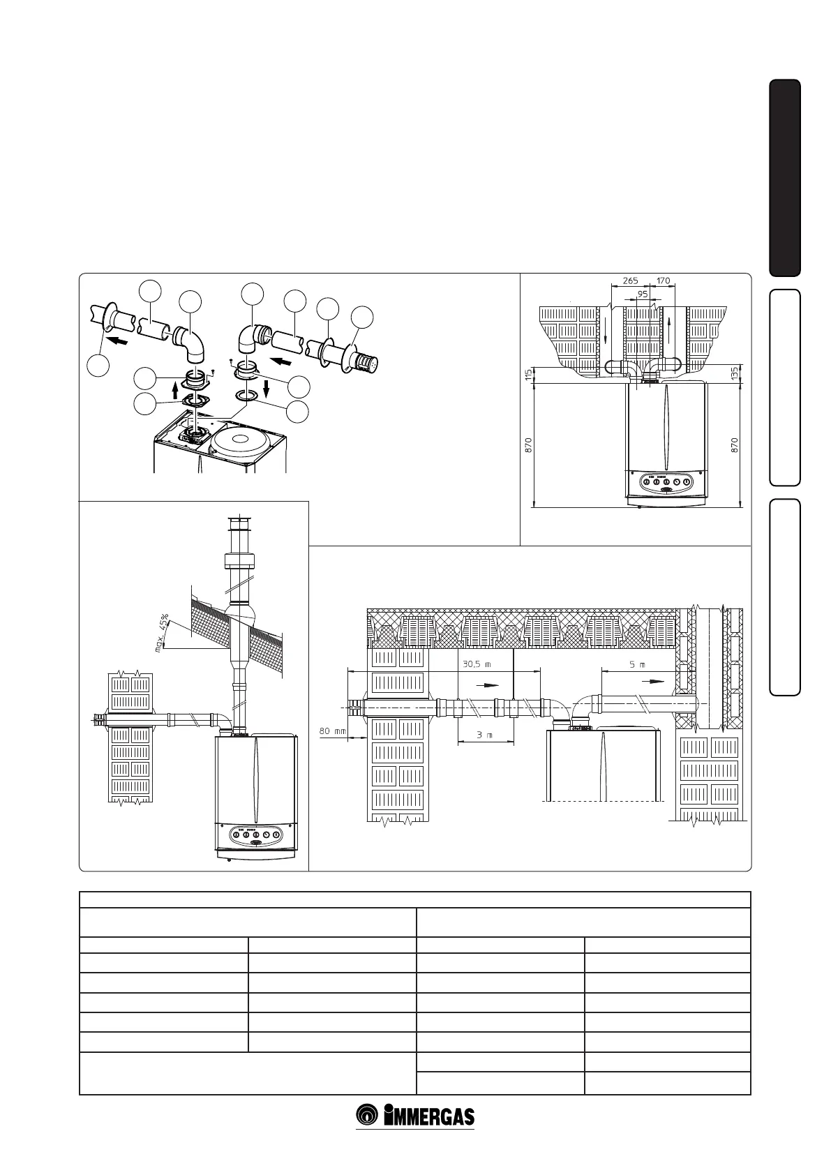
Max. usable lengths (including intake terminal with grill and two 90° bends)
NON-INSULATED
PIPE
INSULATED
PIPE
Exhaust (m) Intake (m) Exhaust (m) Intake (m)
1 36,0* 6 29,5*
2 34,5* 7 28,0*
3 33,0* 8 26,5*
4 32,0* 9 25,5*
5 30,5* 10 24,0*
* e air intake pipe can be increased to 2.5 metres if the exhaust bend is
eliminated, 2 metres if the air intake bend is eliminated, and 4.5 metres
eliminating both bends.
11 22,5*
12 21,5*
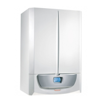
e kit includes:
N°1 - Exhaust seal (1)
N°1 - Female intake ange (3)
N°1 - Flange seal (2)
N°1 - Female exhaust ange (4)
N°1 - 90° bend Ø 80 (5)
N°1 - Intake terminal Ø 80 (6)
N°1 - Internal rings (7)
N°1 - External ring (8)
N°1 - Exhaust pipe Ø 80 (9)
separator Ø 80/80 to a concentric pipe), the
maximum extension can be calculated by
using a resistance factor for each component
or the the equivalent length. e sumof these
resistance factors must not exceed 100.
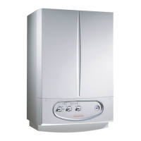
• Temperature loss in fume ducts (Fig. 1-25). To
prevent problems of fume condensate in the
exhaust pipe Ø 80, due to fume cooling through
the wall, the length of the pipe must be limited to
just 5 m. If longer distances must be covered,
use Ø 80 pipes with insulation (see insulated
separator kit Ø 80/80 chapter).
Insulated separator kit Ø 80/80. Kit assembly
(Fig. 1-26): install flange (4) on the central
hole of the boiler, tting seal (1), and tighten
with the at-tipped hex screws included in the
kit. Remove the at ange on the lateral hole
(depending on installation requirements) and
replace with ange (3) inserting seal (2) already
tted on the boiler and tighten using the self-
tapping screws supplied. Insert and slide cap
(6) onto bend (5) from the male side (smooth),
and join bends (5) with the male side (smooth)
in the female side of ange (3). Fit bend (11)
with the male side (smooth) in the female side
of ange (4). Fit the male end (smooth) of the
intake terminal (7) up to the stop on the female
end of the bend (5), making sure you have already
inserted the rings (8 and 9) that ensure correct
installation between pipe and wall, then x the
closing cap (6) on the terminal (7). Join the
exhaust pipe (10) with the male side (smooth) in
the female side of the bend (11) to the end stop,
ensuring that the washer (8) is already inserted
for correct installation between the pipe and ue.
• Coupling of extension pipes and elbows. To
install snap-t extensions with other elements
of the fume exhaust system, proceed as follows:
t the male end (smooth) of the concentric
pipe or concentric elbow up to the stop on the