Relay configuration number can be modified by either the web interface, Modbus register 012 or the Mode
switch.
6. ETHERNET
Description
Can be used to reset network configuration
Slowly blinking when module is powered, permanently lid when link established.
10BASE-T RJ-45 connector.
Indicates Ethernet activity or Modbus reception.
The communications module has a built in web server which allows you to access your pump directly to an
existing Ethernet connection. Direct connection to a computer is also possible with a cross over cable.
The web server uses HTML pages to set/view:
• Regulation mode settings
• Regulation parameters (power, RPM, head, flow, efficiency)
• Relay settings
• External control inputs
• Current and previews error
• Pump statistics (power consumption, run time and other).
7
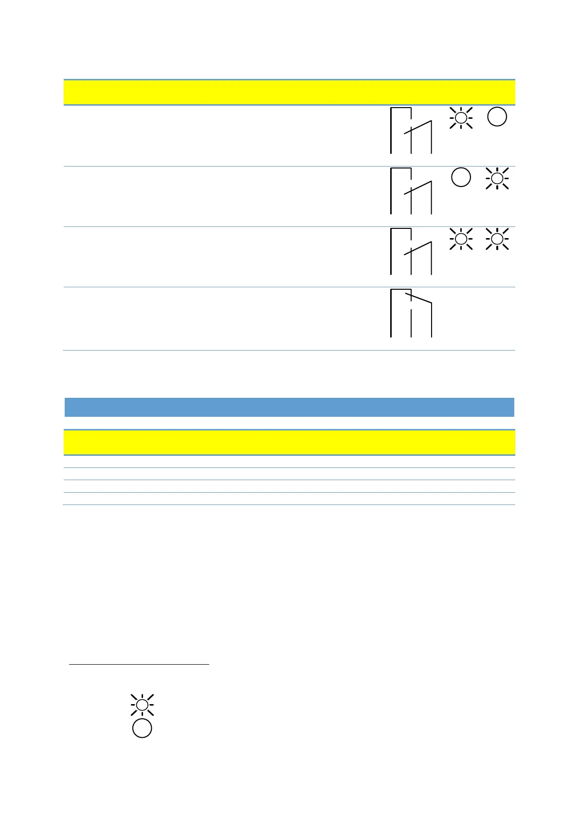
When mode Mode 6 or Mode 7 is selected, LED1 and LED2 will show relay configuration. See section “4.3
Module mode selection”
LED is on
LED is off
Description
[default]
Only active when the pump is powered up
and detects a problem with operation.
The relay signal is active when the pump is
ready for operation.
The relay signal is active as long as the pump
is operating. If the pump comes to a stop or
an error occurs, relay will deactivate.