2.1. SYSTEM DIAGRAM
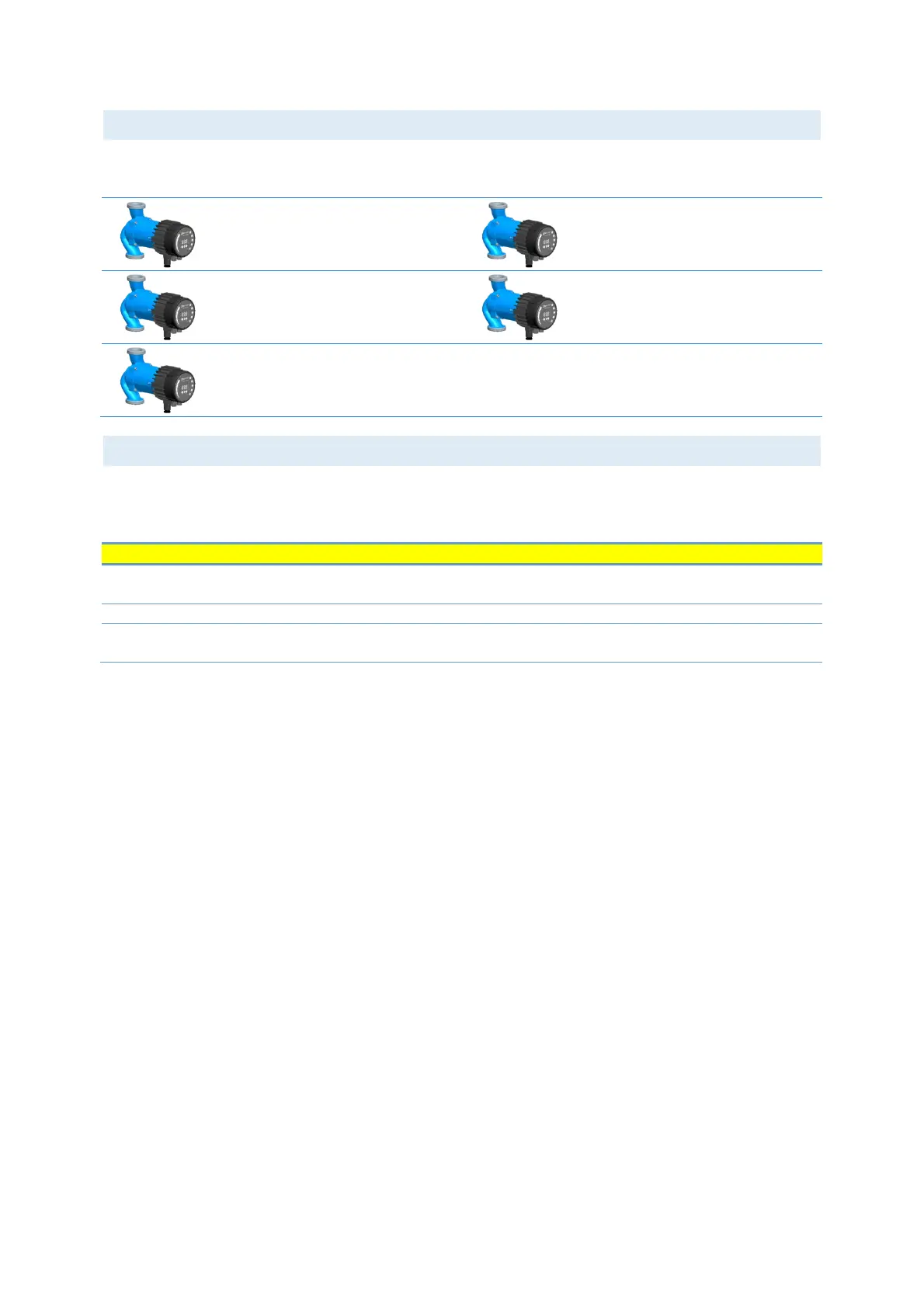
There are several possible connection configurations. Not all functions can be used simultaneously.
on/off + 0..10 V + relay output
Modbus RTU + Relay output
Ethernet + on/off + 0..10 V
Ethernet + on/off + relay output
2.2. SPECIFICATIONS
The table below is an overview of NMTC specifications. For details, please refer to appropriate sections
of this manual.
<95 % relative, non-
condensing
Also see appropriate pump data for other ambient
specifications.
Dimensions without glands.
Power supply and
connection
5 V@500 mA supplied
by the pump
6-pin connector further extended for display.