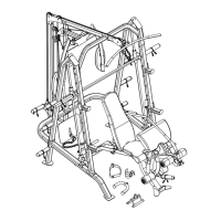
STEP 9 (See Upper Cable Loop & Diagram 9)
A.) Attach the 142” Upper Cable (#44) to the open pulley bracket under the Upper Frame (#17).
Attach a Pulley (#59) to the open bracket. Secure it with one M10 x 1 ¾” Allen Bolt (#95), two
Ø ¾” Washers (#107), and one M10 Aircraft Nut (#110). Make sure the ball stopper on the
Cable is underneath the Upper Frame.
B.) Draw the Cable over the Pulley to the second open bracket under the Upper Frame. Attach a
Pulley to the open bracket. Secure it with one M10 x ¾” Allen Bolt (#95), two Ø ¾” Washers
(#107), and one M10 Aircraft Nut (#110).
C.) Draw the Cable around the Pulley then to the upper opening on the Front Press Base (#18).
Attach a Pulley to the opening. Secure it with one M10 x 5 1/8” Allen Bolt (#103), two Ø ¾”
Washers (#107), two 1 7/8” Spacers (#21), and one M10 Aircraft Nut (#110). Note the
direction of the Bolt shown in Diagram-9-1- C.
D.) Draw the Cable around the Pulley to the upper opening on the Vertical Frame (#7). Attach a
Pulley to the opening. Secure it with one M10 x 3 ½” Allen Bolt (#100) and one M10 Aircraft
Nut (#110).
E.) Draw the Cable around the Pulley to the lower opening on the Front Press Base. Repeat
Procedure C above to install a Pulley.
F.) Draw the Cable around the Pulley to the lower opening on the Vertical Frame. Repeat
Procedure D above to install a Pulley. Draw the Cable around the Pulley then downward.
G.) Attach the Cable to a Double Floating Pulley Bracket (#16). Attach a Pulley to the Bracket.
Secure it with one M10 x 1 ¾” Allen Bolt (#95), two Ø ¾” Washers (#107), and one M10
Aircraft Nut (#110). Draw the Cable around the Pulley then upward to the open bracket under
the middle of Upper Frame. Let the Double Floating Pulley Bracket hanging for now.
H.) Attach a Pulley to the open bracket. Secure it with one M10 x 1 ¾” Allen Bolt (#95), two Ø ¾”
Washers (#107), and one M10 Aircraft Nut (#110).
I.) Draw the Cable to the open bracket under the rear of Upper Frame. Repeat Procedure H
above to install a Pulley.
J.) Draw the Cable around the Pulley then downward between the two Guide Rods (#20) to the
Selector Rod (#25). Attach a M12 Nut (#112) to the head of Cable. Thread the head of the
Cable firmly into the Selector Rod.
20