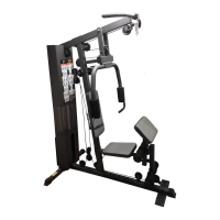
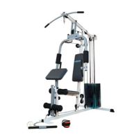
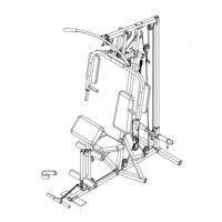
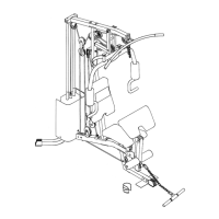
ASSEMBLY INSTRUCTION
Tools Required Assembling the Machine: Two Adjustable Wrenches, two Allen
Wrenches, and one Philips Screwdriver. NOTE: It is strongly recommended this
machine to be assembled by two or more people to avoid possible injury.
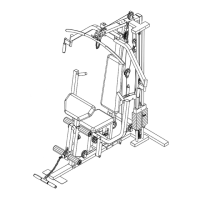
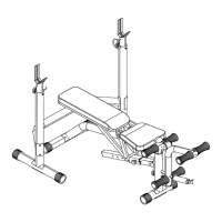
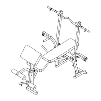
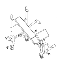
STEP 1 (See Diagram 1)
A.) Connect the two Lower Guide Rods (8) and two Upper Guide Rods (#9) with two Stud
Bolts (#73). Firmly thread the Rods together.
B.) Insert the Lower Guide Rods (#8) into the holes on the Rear Base Frame (#2). Secure
it with two M10 x 1” Allen Bolts (#88) and Ø ¾” Washers (#95) from the bottom.
C.) Slide two Ø 2 ½” x 1” Rubber Bumpers (#58) onto the Guide Rods.
D.) Attach the Main Frame (#1) to the Rear Base Frame (#2). Secure it with two M10 x 2
¾” Carriage Bolts (#80), one 4 3/8” Bracket (#27), two Ø ¾” Washers (#95), and two
M10 Aircraft Nuts (#92).
E.) NOTE: Do not tighten all the Nuts and Bolts until instructed to do so.
F.) Place the other end of Main Frame onto the Front Base Frame (#3). Place the Seat
Support (#5) onto the Main Frame. Align the holes then secure the Seat Support, Main
Frame, and the Front Base Frame together with two M10 x 3 ½” Carriage Bolts (#79),
Ø ¾” Washers (#95), and M10 Aircraft Nuts (#92).
G.) Attach the Front Seat Support (#45) to the Seat Support (#5). Secure it with two M10 x
1 5/8” Allen Bolts (#87) and Ø ¾” Washers (#95).
H.) Attach the Leg Developer Holder (#19) to the Main Frame (#1). Secure it with two M10
x 2 ¾” Carriage Bolts (#80) from the side, one M10 x 3 ½” Carriage Bolt (#79) from the
bottom, three Ø ¾” Washers (#95), and three M10 Aircraft Nuts (#92). Thread the Lock
Knob (#61) into the hole on the Leg Developer Holder.
I.) Attach the two Foot Plates (#33) to the Front Base Frame (#3). Secure them with two
M10 x 2 ¾” Carriage Bolts (#80), Ø ¾” Washers (#95), and M10 Aircraft Nuts (#92).
J.) Attach the Lower Vertical Frame (#6) to the Main Frame (#1). Secure it with two M10 x
3 ½” Carriage Bolts (#79), one 4 ¾” Bracket (#28), two Ø ¾” Washers (#95), and two
M10 Aircraft Nuts (#92).
K.) Attach the Upper Vertical Frame (#7) to the Lower Vertical Frame. Secure them with
four M10 x 2 ¾” Carriage Bolts (#80), two Vertical Frame Brackets (#21), four Ø ¾”
Washers (#95), and four M10 Aircraft Nuts (#92).
L.) Push three Base Frame End Caps (#64) onto the ends of Rear and Front Base
Frames.
7