43
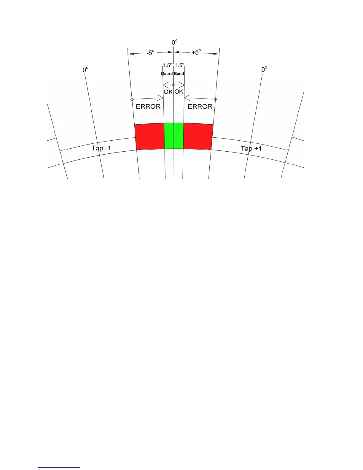
Figure 3.2 On-Tap Example
Figure 3.1 is an example of an LTC with 10.0 degrees per tap position. This LTC
should stop at the “zero degrees” center point on every tap, plus or minus a programmable
tolerance (“Guard Band”) of 1.5 degrees (green area). If the LTC ever stops more than 1.5
degrees from the center (red area) of any tap, the On-Tap Alarm Relay will be asserted and an
LED will flash. The alarm code “OtGLt” will be displayed momentarily.
Use the OP 62, OtGLt, OTGDLMT command to set the On-Tap Guard Band
tolerance in degrees, +/- from zero. Use the OP 63, OtrLY, OTRLY command to select
which relay (OFF, LO or HI) asserts when the On-Tap Guard Band is reached. When this
value is set to “OFF” this function is disabled. Use the OP 63, OtdtE, OTDATE command
to enter a reference date.
Use the OP 65, OtdIS, DUMP command to display each tap and the highest
measured deviation for that tap. Use the UP and DOWN keys to scroll through the list of
taps. Press the ENTER key to select a tap and display its highest measured deviation in
degrees with 1/10
th
degree resolution and (-) sign (example: 1.3 or -0.9). Press the ENTER
key to return to the list of taps. Press the MENU key to escape back to the programming
menu.
Use the OP 66, Otdtd, command (menu only) to display all taps that exceed the
deviation limit. Press the ENTER key to display the measured deviation for each. Use the
UP and DOWN keys to scroll through the list of taps. Press the ENTER key to select a tap
and display its highest measured deviation. Press the Enter key to return to the programming
menu. Use the OP 67, OtrSt, OTRST command to reset all On-Tap logs. This command
will also clear an active On-Tap alarm.