7
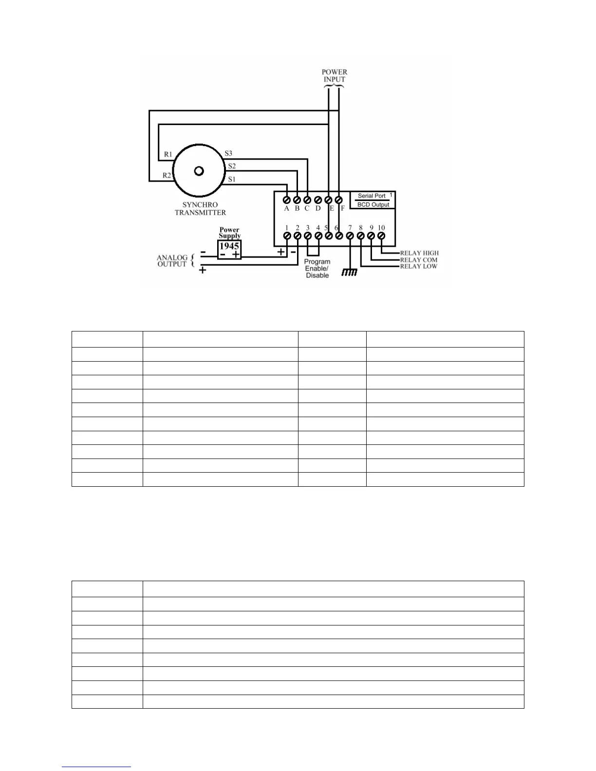
Figure 1.3 Field Wiring Diagram with 4-20mA Output
Table 1.1 Terminal Functions
Terminal Function Terminal Function
A S1 1 Analog Output +
B S2 2 Analog Output –
C S3 3 Program Mode Inhibit
D (Spare) 4 Inhibit Return
E R1 * 5 Line L1 *
F R2 * 6 Line L2 *
7 Chassis Ground
* Terminals E & F are 8 Relay Low Contact N.O.
jumpered to 5 & 6 9 Relay Common
respectively 10 Relay High Contact N.O.
A DIP switch tells the firmware which hardware options are installed, so their function
can be enabled. It is located on the top PCB, above the power transformer and is
accessible through a slot in the left side of the case, towards the rear of the instrument.
Table 1.2 DIP Switch Functions
Switch # Function
1 Serial Communications Option Enable
2 MODBUS Protocol Enable
3 Spare
4 High / Low Relay Limit Option Enable
5 Analog Output Option Enable
6 Spare
7 Spare
8 In-Factory Test & Calibration Menu Enable