LSU Installation Page 2.2 - 13 2.2
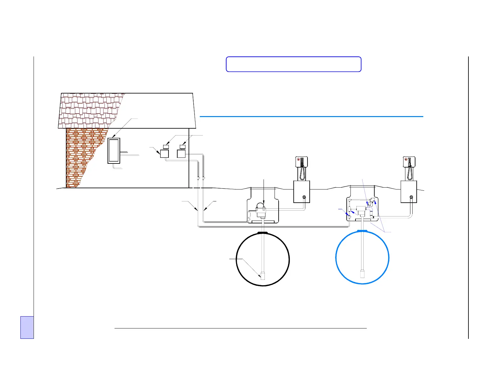
Figure 2.2-14 INCON TS-LLD Installation at External Leak Detector Port
Tank - Pump # 1
("Standard" Single Phase
Installation)
Existin
Conduit
(Pump 1)
TS-LLD CUs
(Control Units):
# 2 and # 1
INCON TS-LLD Line Leak Detector
External Leak Detector Port Installation
Existin
Conduit
(Pump 2)
Submer
ed
Turbine
Pump (STP)
1
Pump
Relay
Boxes
2
Electrical
Power Panel
Epoxy
Filled
EYS
Seal
Fittin
Tank - Pump # 2
Installation within an
External Leak Detector Port
( not pump housing)
Explosion-
proof
Junction
Boxes
TS-LLD LSU (#2)
(Leak Sensin
Unit)
at External Leak Detector Port
TS-LLD LSU (#1)
(Leak Sensin
Unit)
at STP housin
Standard
Sin
le Phase Installation
Dispenser
# A
Dispenser
# X
NOTE:
A TS-TGI Tank Gauge Interface
module is required to connect the
TS-LLD Line Leak Detector system
to an INCON TS-1000 Tank Senti-
nel console. See the TS-TGI Install
Manual.
For TS-1001/2001 Tank Sentinel
consoles, use the LLD /
I
interface
...see the OPTIONAL TS-LLD TANK
SENTINEL ATG CONSOLE
INTERFACE chapter in this manual.
Reference Schematic Figure 2.3 - 8