Control Unit Installation Page 2.3 - 3 2.3
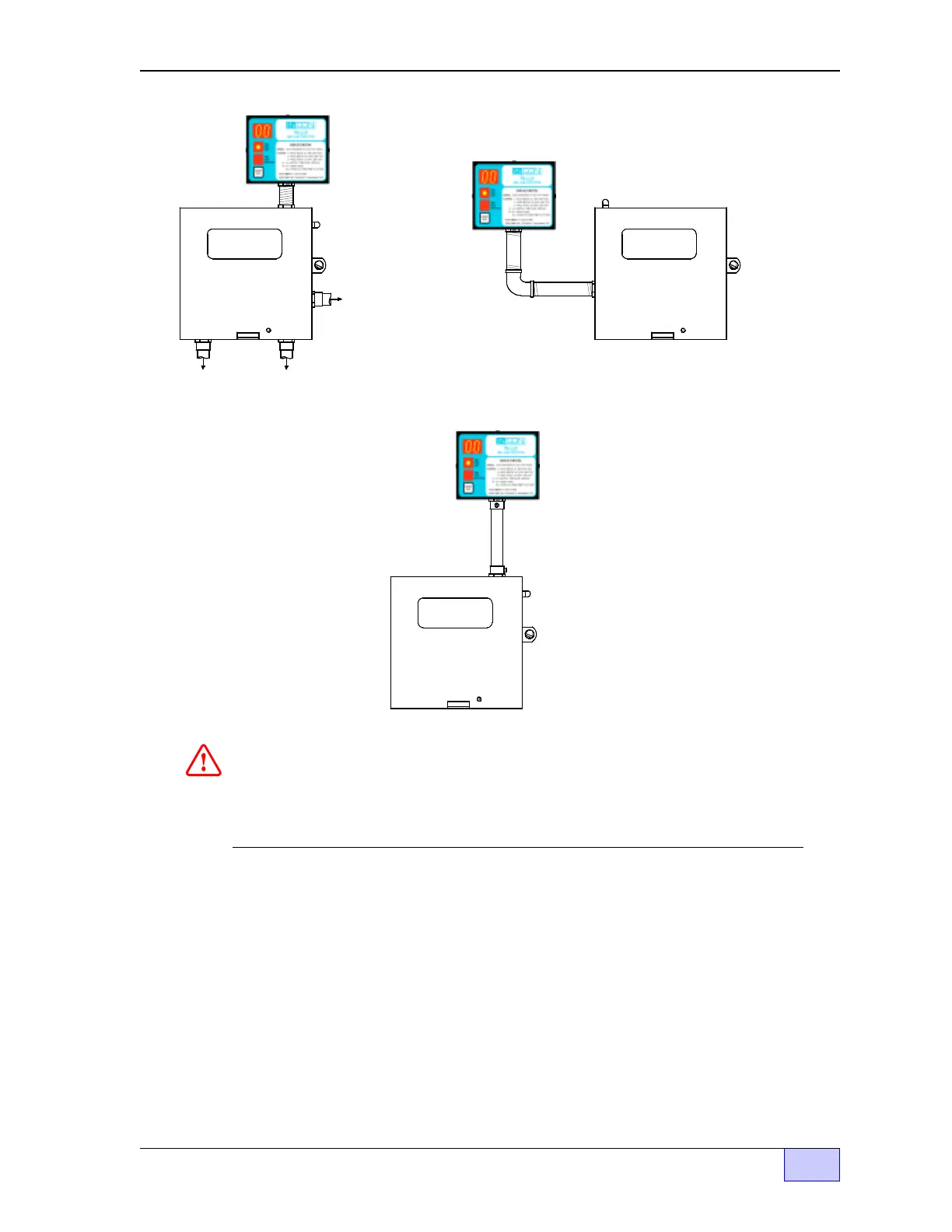
Figure 2.3-3 TS-LLD CU Typical Mounting and Conduit Routing
4) Mount the CU to the pump relay box (see Figure 2.3-3 above for typical
mounting methods). You may mount the control unit to a wall through the two 1/4
inch mounting holes — use fasteners that are appropriate for the wall
construction. The centers of these holes are shown on the inside label of the
control unit. In addition, make sure that the UP arrow is pointing up as shown in
Figure 2.3-2.
WARNING: DISCONNECT POWER
BEFORE REMOVING COVER
PUMP RELAY BOX
WARNING: DISCONNECT POWER
BEFORE REMOVING COVER
PUMP RELAY BOX
To 208/230 VAC
sin
le
hase
Power Source
electrical
ower
anel
- circuit
breakers
To Submersible
Pum
ex
losion
roof Junction Box
To Di s
enser
Switch
es
90° FITTING
- - Alternate Mountin
A - -
NIPPLE
WARNING Avoid electrical shock hazards. Disconnect all electrical power
sources BEFORE removing any enclosure cover !
NOTE: Ground equipment as required by your local and National Electric Codes.
WARNING: DISCONNECT POWER
BEFORE REMOVING COVER
- - Alternate Mountin
B - -
PUMP RELAY BOX
WALL
MOUN TED
& EMT
NOTE
☞