2.3 Page 2.3 - 2 TS-LLD INSTALLATION GUIDE
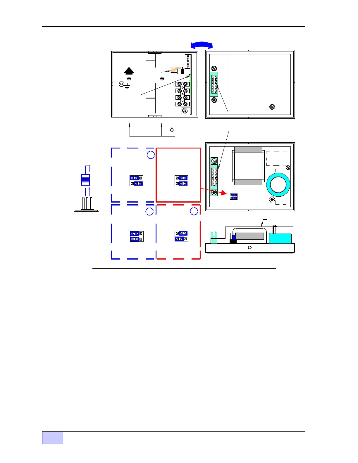
Figure 2.3-2 CU Component Location - Internal View
Control Unit Installation Steps (continued... )
2) Product Configuration (Top Jumper Link) — required only for Diesel, Fuel Oil,
or Kerosene — skip this step if gasoline will be monitored. Remove the plastic
shield in back of the control unit cover. Pull up and reposition the top blue jumper-
link at J2, so that it is installed over the left two pins. See Figure 2.3-2 and
reinstall the plastic shield when done.
3) INCON TS-2000 Configuration (Bottom Jumper Link) — this step is required
only when the TS-LLD will be wired to or interfaced to an INCON model TS-2000
ATG console. Remove the plastic shield from the control unit cover. At J2, pull up
and reposition the bottom jumper-link so that its installed over the left two pins.
See Figure 2.3-2 and the applicable INCON Application Note about wiring to
a TS-2000. Reinstall the plastic shield when done.
Alternate
Jumper
Link Position:
Alternate
Jumper
Link Position:
GAS
DIESEL
GAS
DIESEL
J2J2
for Ga soline
for Diesel, or
Fuel Oils
3
2
Standard TGI
Interface
for
TS-2000 Interface
for
TS-2000 Interface
Standard TGI
Interface
Jumper Link
Side View
TS-LLD CONTROL UNIT (CU) ENCLOSURE
Alternate
Jumper
Link Position:
1
Standard
Jumper
L in k P osi ti on s:
for Diesel, or
Fuel Oils
GAS
J2
for Ga soline
GAS
DIESEL
J2
DIESEL
= 1/4 inch hole
loc ations for
w all mounting.
1 110V
Printed Circuit
Board
(P C Boa rd)
TB 1
2 NEU
3 P-OUT
4 P-IN
SIG RTN
BOX
Donut shaped
Pickup Coil
UP
TB 2
1 485A
2 485B
3 DSY1
4 DSY2
5 ALARM
F1
P L AS TIC S H IE L D S H O W N
MOUNTED OVER PC BOARD.
R E M O VE TH E S H IE L D TO S E T
THE JUMPER LINK POSITION
AS S H OW N BE LO W .
TH IS S H IE L D M U S T B E
IN PLACE BEFORE THE
COVER IS RE-INSTALLED.
Sh ield
Bottom View
C ontrol Unit cover
PC BOARD
GAS
DIESEL
J2
J1
COVER (SHIELD OFF)
GREEN CONNECTOR (J1)
GREEN CONNECTOR (J1)
COVER (SHIELD ON)