Check the installation dimension between the spindle nose end face (5) and
the base body (1) against the size 15
+0.5
mm (in “Clamp open” position).
Observe the installation position.
Alternatively, the following procedure can be used!
If the installation dimension is not correct, turn the base body forward or
backward, until the setting dimension is achieved. Observe the installation
position.
7.
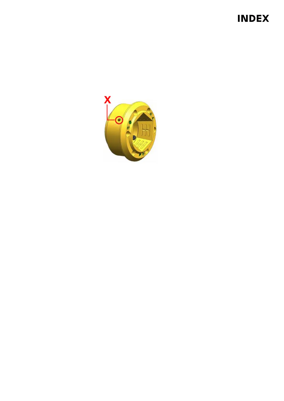
Example: Close TOPlus on cooling lubricant device through main spindle
X
Bonded (Loctite
®
221) set screw
Check the clamping element holder. Valid for all machines MS32-6.3, MS40-6
and MS40-8 with TOPlus clamping system, robot and cooling lubricant device
through the main spindle. Before reinstalling the clamping element holder,
make absolutely sure that the holes marked X are closed with set screws. The
set screws must be screwed down to the bottom of the hole and bonded with
Loctite
®
221.
8. Place the clamping element holder (2) on the spindle nose face (5) and screw
in 6 screws.
9. Tighten the 6 screws (3) crosswise to a torque of 14.9 Nm.
10. Insert collet (4).
11. Be sure to remove the spindle lock (device/locking pin) after finishing
the work.
Maintenance Summary - Care activities
43
Maintenance Instructions
MS40-6
DIM021EN - 03.06.2020