External CT Clamp
Chargers required to utilise Load Curtailment or Solar Mode features, must have an External
CurrentTransformertted,sothechargercanmonitortotaldemandontheinstallationand
totalexportofanymicro-generation.
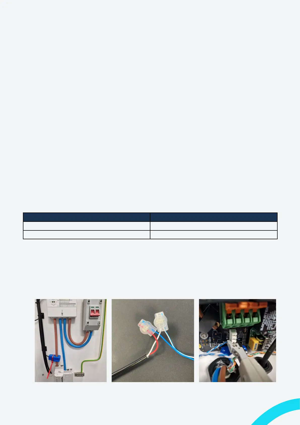
• The External CT clamp must be clipped around a Live cable that will enable it to
measurethetotalimportandexportoftheentireinstallation.Thisisusuallythemain
tailsatthemeter.
Note: The smart charge regulations dictate that metering equipment for EVSE is designed in
suchawayastoprevent/detertampering.
• The hard-wired cable of the CT should be routed to a location where it can be
joinedwithadatacable.Thiswouldusuallybeajunctionboxneartheswitchgearof
thechargercircuit.
Note: Indra recommend the use of EV Ultra Cable from Doncaster Cables as it contains
poweranddatacombinedinonecable.
• Usingthejellycrimpsprovided,jointheCTclampwirestotheBlue/BlueWhitepairof
yourdatacableandsecureitinsideamaintenancefreeenclosure.
Data Cable Conductor CT Clamp Contector
Blue Red
Blue & White White
• Route the data cable to the charger and enter the bottom through an appropriately
sized IP68 gland (If using EV Ultra, it will go through the hole drilled for
thepowercable).
• Using an IDC punch-down tool terminate the Blue/Blue White wires into the CT
connector.
Figure 17: Example CT Location Figure 18: Data Cable Jelly Crimps Figure 19: Charger CT Termination
28 Indra Smart Range Installation Guide