AP29000
Connecting C166 and C500 Microcontroller to CAN
The Controller Area Network (CAN)
Application Note 16 V 1.0, 2004-02
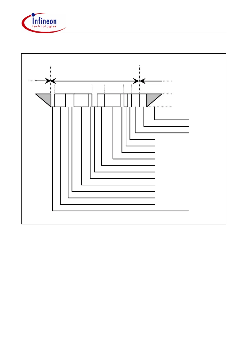
Figure 4 Extended CAN Remote Frame
3.3.3 Error Frames, Overload Frame, Interframe Space
3.3.3.1 Error Frames
An Error Frame is generated by any node that detects a bus error. An error frame
consists of 2 fields, an Error Flag field followed by an Error Delimiter field. The Error
Delimiter consists of 8 recessive bits and allows the bus nodes to restart bus
communications cleanly after an error. There are, however, two forms of Error Flag
fields. The form of the Error Flag field depends on the “error status” of the node that
detects the error (see section 2.5 for details of “error status”).
Inter Frame Space
1
11
4
15 7
3
11 1
1
1
Bus Idle
Intermission
End of Frame
Data Length Code
Start of Frame
18
}
ACK Delimiter
ACK Slot
CRC Delimiter
CRC Sequence
}
}
CRC Field
21
SRR Bit (R)
(2 reserved (D))
Identifier
IDE Bit (R)
Extended Identifier
}
Control Field
(plus IDE Bit)
Acknowledge
Field
Arbitration Field
(without IDE Bit)
Extended Remote Frame
RTR Bit (R)
dominant Level
recessive Level
 Loading...

