AP29000
Connecting C166 and C500 Microcontroller to CAN
The Controller Area Network (CAN)
Application Note 11 V 1.0, 2004-02
3.3 The different CAN Frames and their Formats
3.3.1 Data Frame
3.3.1.1 Standard CAN Data Frame
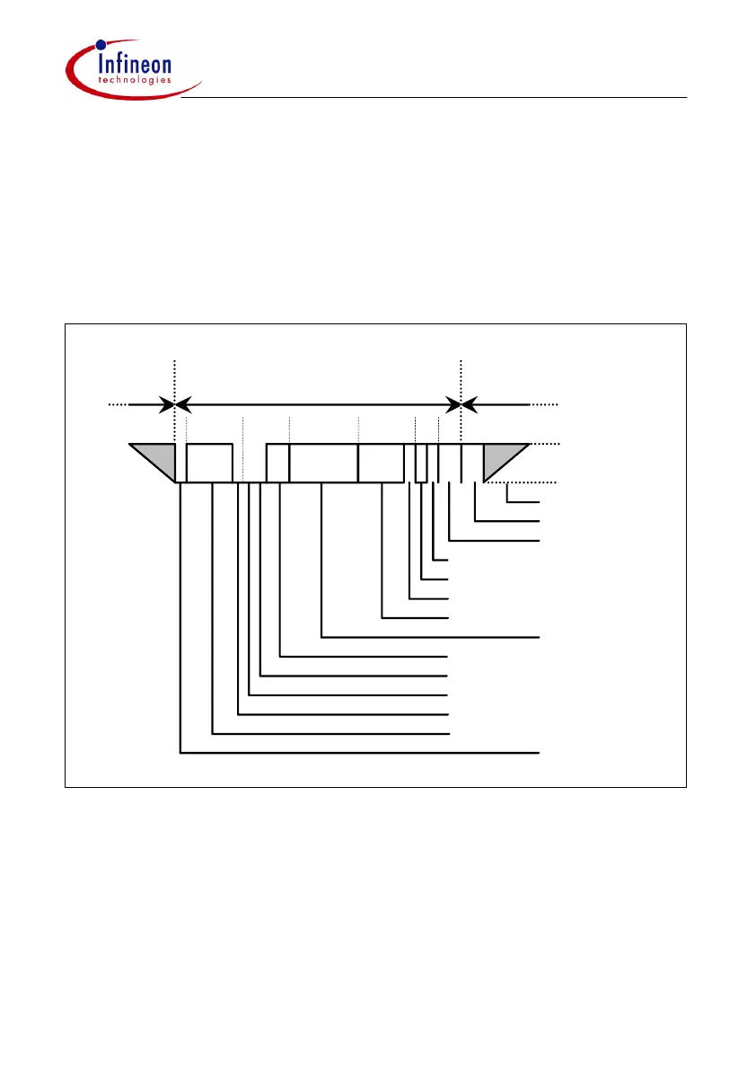
Figure 1 Standard CAN Data Frame
A "Data Frame" is generated by a node when the node wishes to transmit data. The
Standard CAN Data Frame is shown in figure 1. In common with all other frames, the
frame begins with a Start Of Frame bit (SOF = dominant state) for hard
synchronization of all nodes.
Inter Frame Space
111
4
0...64 15 7
3
111 11
1
Standard Data Frame
Bus Idle
Intermission
End of Frame
ACK Delimiter
ACK Slot
CRC Delimiter
Data Field
Data Length Code
Identifier Field
Start of Frame
}
Control Field
CRC Sequence
}
}
CRC Field
}
Arbitration Field
(reserved (D))
IDE Bit (D)
RTR Bit (D)
Acknowledge
Field
recessive Level
dominant Level
 Loading...

