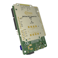
Using Infineon’s radar baseboard XMC4700 and BGT24LTR11 radar
shield with Arduino
Set-up guide
Figure 16 Accessing example sketches from this library
Table 4 Example sketches
Radar_Pulsed_Doppler
_LED
Radar baseboard XMC4700 and BGT24LTR11 radar
shield
Use on-board LED to
indicate detection of
motion and direction
of motion
RadarPulsedDoppler
_Andee_RGB
1) Radar baseboard XMC4700 and BGT24LTR11 radar
shield
2) Annikken Andee U shield
(https://www.annikken.com/andee-u)
3) RGB LED lighting shield with XMC1202
(https://www.infineon.com/cms/en/product/evaluation-
boards/kit_led_xmc1202_as_01/)
Project and display the
results of radar
processing on a smart
device (e.g. cell
phone/tablet) via
Bluetooth, and at the
same time using an
external RGB LED to
indicate motion and
direction of motion
3.4.1 Example 1: Radar_Pulsed_Doppler_LED
This section lists the steps to follow to get this example up and running.
1. In Arduino IDE, navigate to File > Examples > IFXRadarPulsedDoppler > Radar_Pulsed_Doppler_LED (as shown
previously in Figure 16). The sketch will open (Figure 17).

 Loading...