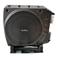
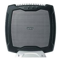
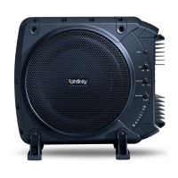
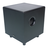
DISASSEMBLY PROCEDURE FOR BASSLINK T (ACCESS TO AMPLIFER, DRIVERS)
1) On a protected work surface, stand the unit up so the back panel is facing you.
2) Remove the (12) Phillips screws holding the black heatsink to the enclosure. Do not remove the
heatsink at this time.
3) Remove the (36) Phillips screws holding the back panel to the main enclosure. Note in the area of the
heatsink, two screws are shorter, machine screws.
4) Carefully separate the back panel from the main enclosure; try not to damage the O-ring that may be
adhered to both sides of the enclosure, preventing its separation. Note the LED wires from the
heatsink area routed to the amplifier; unplug the 2 lead connection at female connector M2 on the
amplifier. Set the heatsink and LED w/ wires aside.
5) Unplug the woofer wires from the terminals.
6) Completely separate the two enclosure halves.
SERVICING THE INPUT/PREAMP SECTION
7) Remove the (8) Phillips screws holding the cover plate to the enclosure.
8) With a wood chisel or similar tool, carefully pry the plastic cover away from the cup, working around the
perimeter, until the cover is detached. If the cover is damaged during this procedure, order
part# 309-ABS-05002.
REASSEMBLY
9) If the cover to input/preamp section was detached, apply a bead of silicon sealer or similar adhesive
around the perimeter of the cover, in the sealing groove. Without this adhesive, there may be an air
leak which would affect performance. Press the cover into place.
10) Attach the woofer wires.
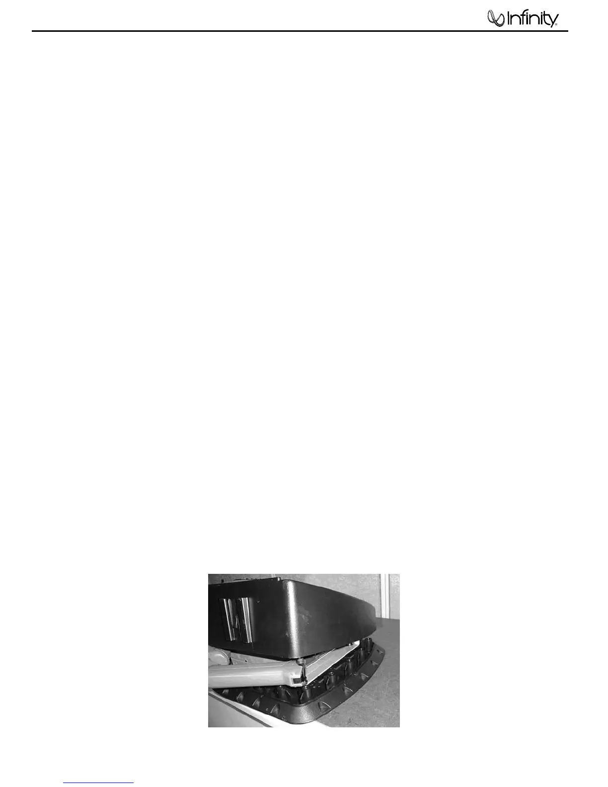
11) Before the enclosure can come together, connecting the heatsink/LED wire presents a challenge if not
correctly done. The LED wire must thread through the enclosure, the small hole in the aluminum
heatsink plate, and back into the M2 connector on the amplifier. The position in which this is best
achieved is with Basslink T laying flat side down on a surface, woofer side up. Partially bring the
enclosure halves together, and work through the remaining gap near the heatsink end. See illustration.
12) Make sure the O-ring around the perimeter of the enclosure is intact and in place. Make sure the two
shorter machine screws are used in the back panel, in the area near the heatsink.
13) Replace all enclosure and heatsink screws.
BassLink T
 Loading...