APPLICATIONS
For your convenience, we’ve included several application
diagrams to help you plan your own system installation.
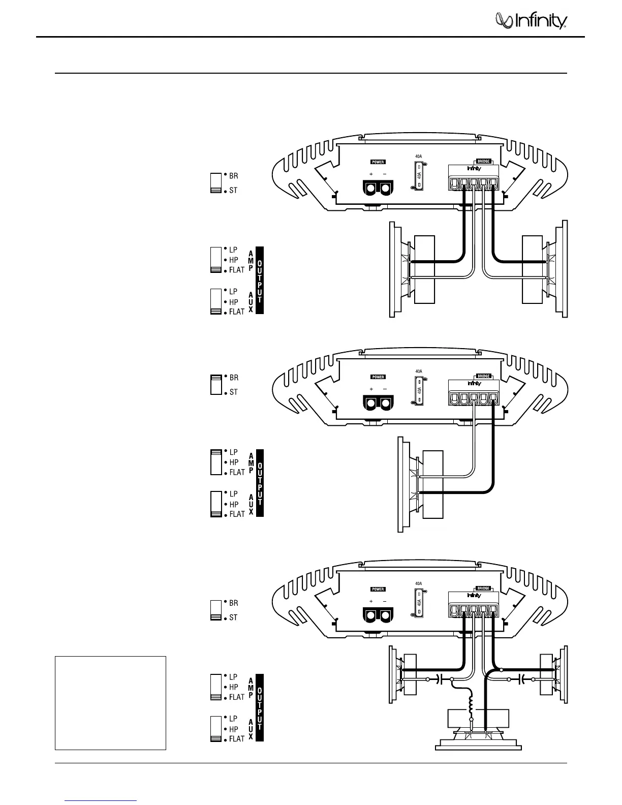
Figures 1 through 3 show how to configure the Kappa 102a
for stereo, bridged-mono, and tri-mode operation.
For system expansion ideas, see the next page.
NOTE: For simplicity, Figures 1 through 3 do not show power,
remote, and input connections.
KAPPA 102a
(rear panel)
REM
–
R
+
–
+
L
+
-
+
-
R Speaker
L Speaker
Set Mode Switch
To STEREO
(on top panel)
Set Filter Switches
To FLAT
(on top panel)
KAPPA 102a
(rear panel)
REM
–
R
+
–
+
L
+
-
+
-
-
+
R Speaker
Subwoofer
L Speaker
Set Mode Switch
To STEREO
(on top panel)
Set Filter Switches
To FLAT
(on top panel)
CapacitorCapacitor
Inductor
Figure 1. This wiring diagram
shows a Kappa 102a amplifier
set to stereo to drive a pair of
full-range speakers.
Figure 2. This wiring
diagram shows a Kappa
102a amplifier set to
bridge (mono) to drive a
single subwoofer.
Figure 3. This wiring diagram
shows a Kappa 102a amplifier
set for tri-mode operation. For
a desired crossover frequency,
use the chart to select a low-
pass inductor for the sub-
woofer, and corresponding
high-pass capacitors for left
and right speakers.
KAPPA 102a
(rear panel)
REM
–
R
+
–
+
L
-
+
Set Mode Switch To
BRIDGE
(on top panel)
Set Filter Switches
(on top panel)
Subwoofer
FREQUENCY INDUCTOR CAPACITOR
Crossover 6 dB/oct. LP 6 dB/oct. HP
(4 ohm) (4 ohm)
75Hz 8.0 mH 530 µF
100 Hz 6.4 mH 400 µF
125 Hz 5.0 mH 318 µF
150 Hz 4.2 mH 265 µF
175 Hz 3.6 mH 227 µF
200 Hz 3.2 mH 198 µF
Kappa 102a