Copyright ©2018, Infoblox, Inc.All right reserved.
Infoblox 800 Series Hardware Components
The Infoblox 800 Series are 1-U platforms that are installed in a standard equipment rack. For information, see Infoblox 800 Series Rack Mountin
. Front panel components include communication ports and indicator lights. Back panel components include the air vent, power g Procedures
connector, on/off switch, and fans.
Appliance Front Panel
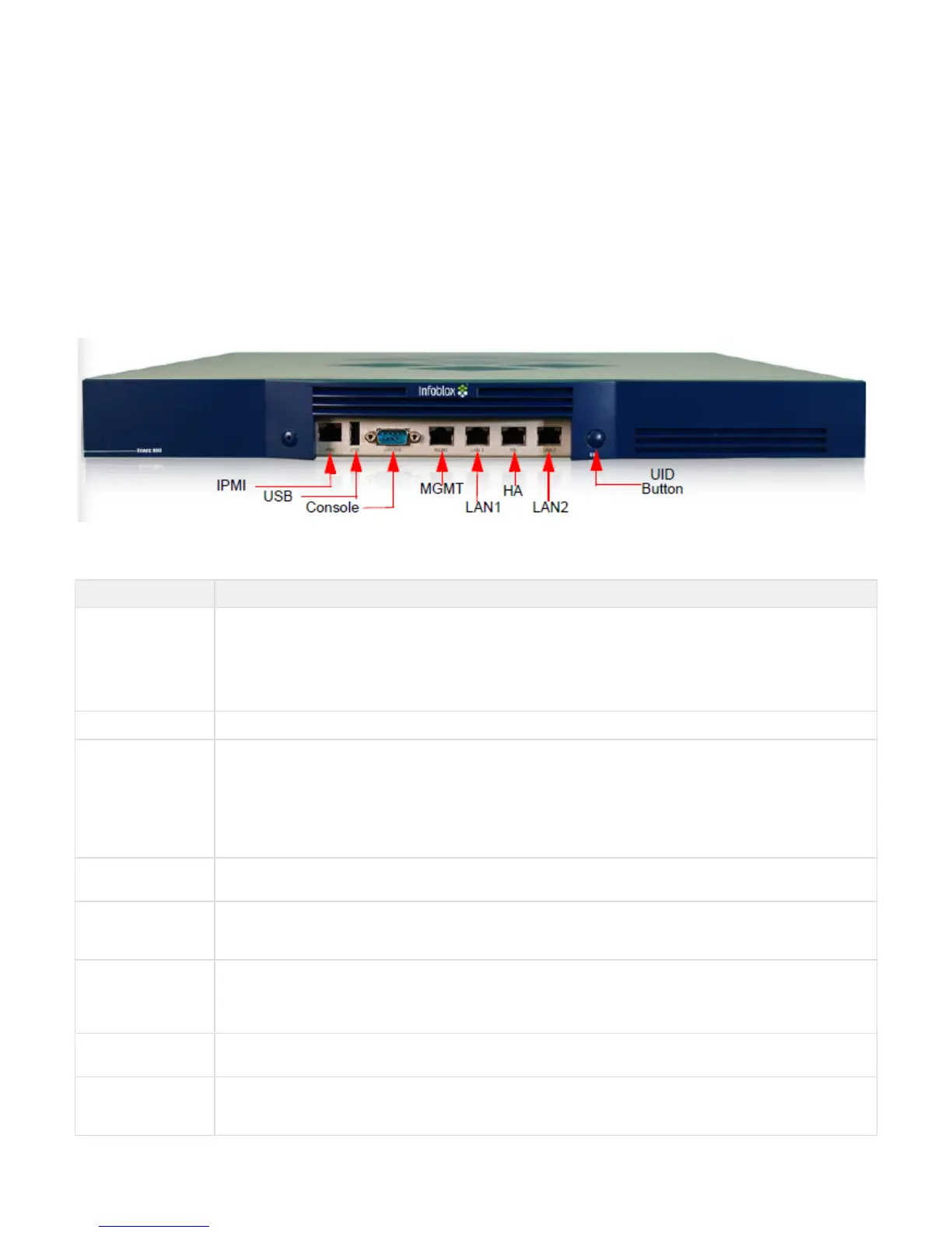
The Infoblox 800 Series front panel components are shown in and described in . For explanations of the Ethernet port LEDs, and Figure 1 Table 1
console and Ethernet port connector pin assignments, see and . Ethernet Port LEDs Interface Connector Pin Assignments
Figure 1 Infoblox 800 Series Appliance, Front View
Table 1 Infoblox 800 Series Front Panel
Component Description
IPMI Port Dedicated Ethernet port used for LOM (Lights Out Management) with specific releases of NIOS. The IPMI/LOM Port
supports 10/100/1000 Mbps operation only. Ensure that the IPMI port is properly connected to the network before you
configure LOM through the Infoblox Grid Manager for remote management. The IPMI/LOM port auto-negotiates up to
Fast Ethernet 100BASE-TX speeds; ensure that the switch port to which the IPMI port connects will auto-negotiate to
100Mbps operation. Follow best practices for IPMI usage in the network by not allowing the LOM port to connect to
the general-use data center network or to 1 Gbps/10 Gbps switch interfaces.
USB Port Reserved for future use.
Console Port A male DB-9 serial port for a console connection to change basic configuration settings and view basic system
functions through the CLI (command line interface).
Should you need to use a USB-to-Serial adapter to carry a serial connection over a USB port in a computer that lacks
a 9-pin serial interface, use a properly grounded USB-to-Serial dongle to connect to the serial console port. If the
dongle connects to a laptop, the laptop also must be properly grounded. Failure to do so may result in damage to the
serial console port of the Infoblox appliance. Infoblox is not responsible for such damage. For DB-9 pin assignments,
see . Figure 3
MGMT Port A 10/100/1000-Mbps gigabit Ethernet port that you can use for appliance management, or for appliance services on
the network. You can enable the MGMT port and define its use through the Grid Manager after the initial setup.
LAN1 Port A 10/100/1000-Mbps gigabit Ethernet port that connects a NIOS appliance to the network. You must use the LAN1
port to set up the appliance initially. It handles all traffic if you do not enable the MGMT and LAN2 ports. The passive
node in an HA pair uses this port to synchronize the database with the active node.
HA Port ( inactive and r
eserved for future use
in the ND-800 and
)TR-800
A 10/100/1000-Mbps gigabit Ethernet port through which the active node in an HA (high availability) pair connects to
the network using a VIP (virtual IP) address. HA pair nodes also use their HA ports for VRRP (Virtual Router
Redundancy Protocol) advertisements.
Network Insight ND-800 and TR-800 Reporting only: HA Port inactive and reserved for future use.
LAN2 Port A 10/100/1000-Mbps gigabit Ethernet port that connects a NIOS appliance to the network. The LAN2 port is disabled
by default. You can enable the LAN2 port and define its use through the Grid Manager after the initial setup.
UID Button The unit identification button. Pressing the UID button illuminates the blue UID LED on the rear panel. In a rack
environment, the UID feature enables easier location of a server when moving between the front and rear of the rack.
You can also identify the appliance through the Infoblox Grid Manager and CLI command.
 Loading...