According to EN 62040-1-2, the user shall place a warning label on the input distribution panel
and the other primary power isolators, in order to prevent the risk of electric shock caused by a
fault voltage on the UPS. The label shall carry the following wording:
Isolate uninterruptible power supply before working on this circuit
2nd5 Connections
Connections shall be done by authorized technical staff only.
When the UPS is brought from a cold place to a warmer place, humidity of the air may
condensate in it. In this case, wait for two hours before beginning with the installation.
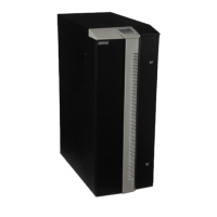
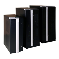
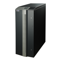
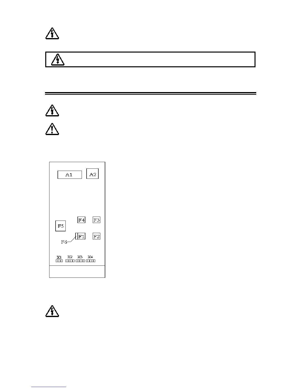
Layout of the connection terminals and boards are shown below:
A1: Communication interface board
A2: Parallel connection board (optional)
F1: Input circuit breaker
F2: Output circuit breaker
F3: Manual by-pass circuit breaker
F4: By-pass circuit breaker (optional)
F5: Battery circuit breaker
F6: Inrush fuse
X1: Battery terminals
X2: Input mains terminals
X3: Separate by-pass mains terminals (optional)
X4: Output terminals
2nd5.1 Power Connections
Devices with internal batteries may have dangerous voltages on the battery terminals
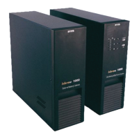
The power screw terminals are located on the lower front side of the UPS. Terminal details for ups’s are
shown separately in the below figures. Refer to the names of each terminal to identify it during
connection:
 Loading...