11
CD1-k – User Guide
Chapter 2 – Commissioning
4.2.2 - CURRENT LIMITATION IN "LIMITING" MODE
When the amplifier output RMS current (I
2
t) reaches 85 % of the rated current, the OK LED on the amplifier front
panel is blinking. When the RMS current (I
2
t) drops below 85 % of the rated current, the blinking is inhibited.
When the amplifier output RMS current (I
2
t) reaches the rated current value, the I
2
t protection limits the amplifier
output current at this value.
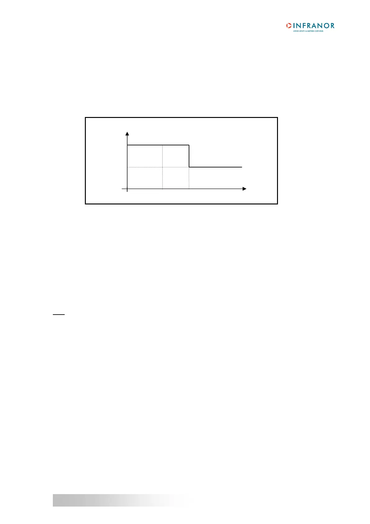
Diagram of the amplifier output current limitation in an extreme case (motor overload or shaft locked):
The maximum current duration before release of the blinking display (t1 - t0) and before limitation at the rated
current (t2 - t0) is calculated the same way as in the "Fusing" mode.
4.3 - SERVO LOOP ADJUSTMENT
4.3.1 - REGULATOR PARAMETERS
The Autotuning procedure identifies the motor and load specifications and calculates the speed/position loop
parameters.
In P and PI speed mode, only the speed loop gains are calculated.
In PI
2
speed mode, the proportional gain of the position loop is also calculated. But the Feedforward gains of the
position regulator are all initialized at 0.
In Position mode, all gains of both speed and position regulators are calculated.
Note: The position loop stability can be tested in PI² speed mode because the Feedback gains are identical to the
Position mode.
The operator can select a bandwidth (Low, Medium or High) as well as the filter type (standard,
antiresonance or max. stiffness).
The Autotuning procedure can be executed with the motor disabled or enabled (i.e. vertical load).
Before executing the Autotuning procedure, check that the motor shaft is free and that its rotation over one
revolution is not dangerous for operator and machine. Check that the brake is released (the Autotuning
command does not control the brake).
For a complete adjustment, the Autotuning procedure must always be executed in Position mode (at power on,
the amplifier is automatically in Position mode).
But the amplifier position loop stability can also be tested in Speed mode. In this case, after the execution of the
Autotuning procedure in PI² mode:
• check that the motor is correctly running in both directions,
• check the response at a small displacement without I
dc saturation (oscilloscope function).
In case of loud noise in the motor at standstill or when running, check the rigidity of the mechanical transmission
between motor and load (backlashes and elasticities in motor and couplings).
If required, start a new Autotuning procedure by selecting a lower bandwidth.
If the instability remains, start a new Autotuning procedure by activating the Antiresonance filter. If necessary,
adjust more accurately the loop response stability by adjusting the stability gain.
Amplifier output current
Max. current
Rated current
time
t0
t1 = Blinking
t2 = Current limitation
t2
t1