13
CD1-k – User Guide
Chapter 2 – Commissioning
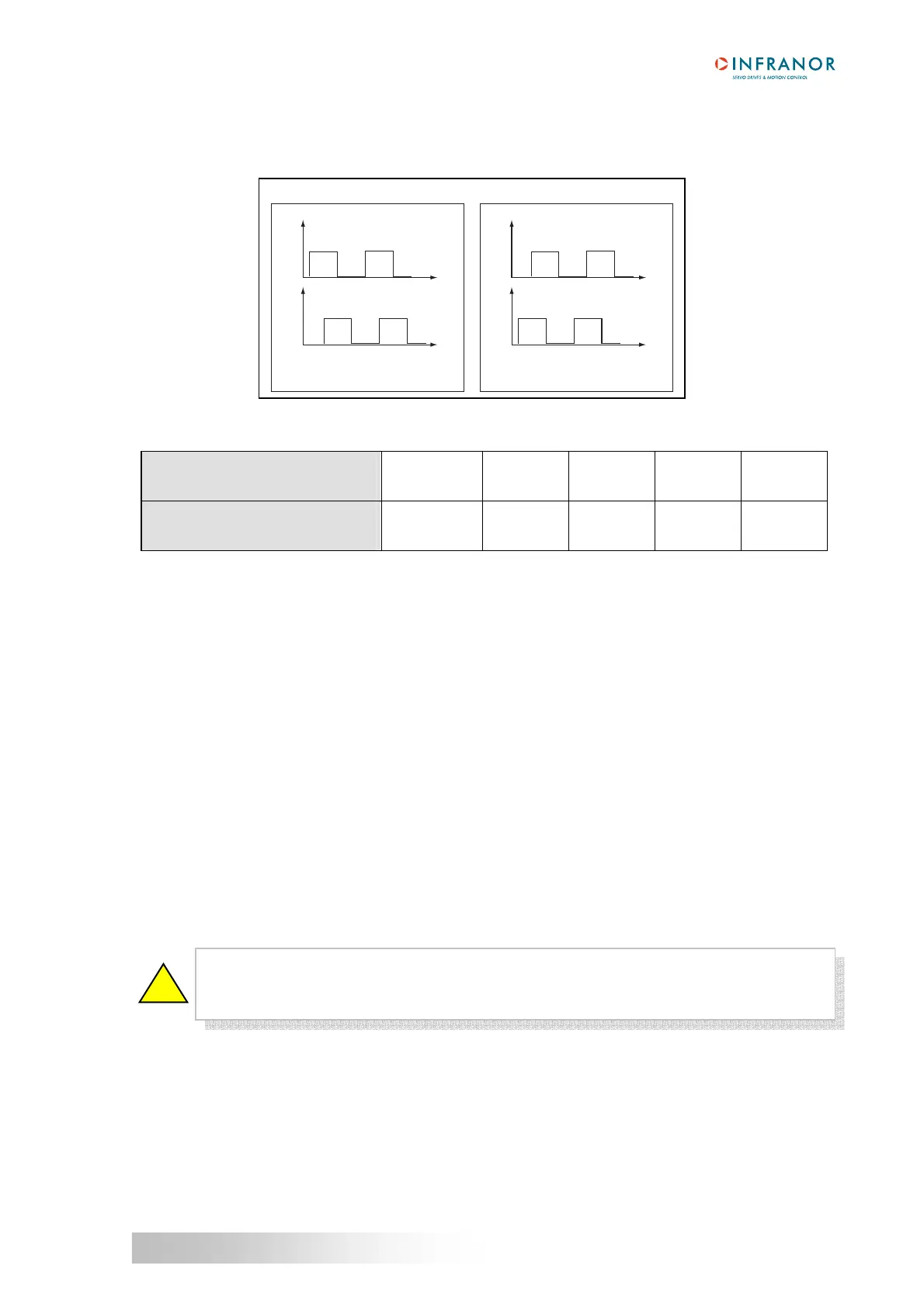
7 - INCREMENTAL ENCODER OUTPUTS
The incremental encoder outputs are two pulse channels A and B in quadrature and one Z marker pulse per
revolution.
The Output encoder resolution is selected according to the table below:
Maximum motor speed (rpm)
up to 1600
up to 3200
up to 6400
up to 12800
up to 25000
Encoder output resolution (ppr)
512 to 16384
512 to 8192
512 to 4096
512 to 2048
512 to 1024
The resolution value defined in the Output encoder resolution parameter can be devided by 2, 4 or 8 by
selecting the Resolution division ratio parameter.
The Output encoder deadband parameter introduces a deadband at standstill around the current resolver
position in order to avoid oscillations of +/- 1 encoder edge on channels A and B. The value of 4095 corresponds
to 1/16 revolution of the motor shaft.
The Zero pulse origin shift parameter allows the shifting of the marker pulse position on channel Z with regard to
the resolver zero position. The value 32767 corresponds to one revolution of the motor shaft. The marker pulse
width is equal to ¼ of the A and B channels period.
8 - COGGING TORQUE COMPENSATION
The cogging torque in brushless permanent magnet rotating motors or the cogging force in brushless permanent
magnet linear motors results from the interaction between the rotor magnets and the stator slots. This disturbance
is due to the difference of reluctance between the copper of the windings and the iron of the stator teeth. For a
given motor, the cogging can be easily evaluated by simply moving the motor manually when the amplifier is
disabled. The Cogging compensation option available in the CD1 amplifier range allows to cancel the motor
cogging effects for specific applications where torque accuracy or force accuracy higher than 1 % is required.
CD1 amplifiers must be factory set for getting the cogging compensation option (reference CD1k-U/I–CT). Check
for the presence of the cogging compensation option (CT-CD1) in the VDSetup Hardware option menu. In this
case, the Cogging torque compensation menu can be selected in the Servo loop module.
The cogging torque acquisition procedure is started by means of the Start button. The motor must be uncoupled
from its load and the shaft must not be disturbed during the procedure. Before starting the acquisition, switch the
drive on manual mode and then disable it (Drive control = Off). Then, start the Auto-tuning procedure with
following selections: Regulator = PI², Filter = Max. stiffness and Bandwidth = High. At the end of the cogging
torque acquisition procedure, the amplifier parameter file (*.PAR) can be uploaded again in order to recover the
initial adjustments.
For a brushless motor equipped with an incremental encoder, the Cogging torque
compensation is only available if the encoder is providing one marker pulse per motor
revolution.
!
A
B
A
B
CW rotation
(motor shaft front view)
CCW rotation
(motor shaft front view)
t
t
t
t