EasyManua.ls Logo

Ingersoll-Rand 247PD5-P - User Manual

Ingersoll-Rand 247PD5-P
15 pages
Print Icon
To Next Page IconTo Next Page
Loading...
PL-MANW
Rev.B, Nov’20
- 1 -
Contents: Page:
Safety Precautions 2
Preventative Maintenance Schedule 3
Unpacking and Inspection 4
Installation – Mechanical 5
Lubrication 6
Installation – Electrical 7-8
Start-up Procedures 9
Trouble-Shooting Guide 10-13
Ingersoll-Rand Limited Warranty 14-15
Please read this manual before
installing or using your Air
Compressor Unit. It contains
valuable information that will
help in the receiving,
installation, use, and
maintenance of the Unit.
Please keep this manual in a
safe place for future reference.
All of the information, policies, and
procedures in this reference manual apply
exclusively to Ingersoll Rand.
Pressure Lubricated
Air Compressor
Installation,
Maintenance,
And
Service Data
Ingersoll Rand
490 Welham Road,
Barrie, ON L4N 8Z4, Canada
Tele: 1-800-483-4981
Web: www.ingersollrand.com
Email: AirPS@irco.com
Question and Answer IconNeed help?

Do you have a question about the Ingersoll-Rand 247PD5-P and is the answer not in the manual?

Overview

This document is a comprehensive manual for the Ingersoll Rand Pressure Lubricated Air Compressor, providing detailed information on its installation, maintenance, and service.

Function Description:

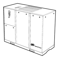
The Ingersoll Rand Pressure Lubricated Air Compressor is designed to compress air for various applications. The manual emphasizes safe and correct operation, highlighting important points related to user safety and preventing equipment problems. It covers aspects from initial setup to troubleshooting, ensuring the unit operates efficiently and reliably. The compressor units are extensively tested at the factory before shipment to ensure quality and performance.

Important Technical Specifications:

  • Voltage Requirements: For 3-phase motors, the voltage variance is 230 volts +/- 10%. A 208-volt 3-phase electrical supply requires the unit to be 200 volts. For single-phase motors, the voltage variance is 230 volts +/- 10%, with a 208-volt power supply requiring a transformer to increase the voltage to 230 volts.
  • Motor Horsepower: The manual references installation kits for different horsepower ranges: IK515 for 5 to 15 HP and IK2530 for 25 and 30 HP.
  • Ambient Temperature: The compressor should operate in an ambient temperature range of 50°F to 104°F (10°C to 40°C).
  • Air Pressure Capability: The compressor is capable of producing pressures greater than 50 psi.
  • Ventilation: One horsepower produces approximately 2500 BTU/HR. For example, a 15 HP unit generates 37,500 BTU/hour, necessitating adequate ventilation in a compressor room.
  • Clearance: A minimum of 18 inches (0.5 m) around and 24 inches above the unit is required for proper ventilation and ease of servicing.
  • Motor Rotation: When facing the compressor, the flywheel must rotate in a clockwise direction. For 3-phase power, if rotation is incorrect, L1 and L3 at the input into the Magnetic Starter should be switched.
  • CPR Valve Minimum RPM: The CPR Valve requires a minimum of 500 rpm to close.

Usage Features:

  • Indoor Use Only: To reduce the risk of electric shock or injury, the compressor must be used indoors.
  • Anchoring: All compressor units must be anchored to the floor as shown in the manual to prevent damage and ensure tank warranty validity. Vibration pads (UDH-9700), stainless steel flex hose, and steel and rubber washers are available in installation kits for this purpose.
  • Location Requirements: The unit must be located indoors in a dry, clean, cool, dust-free, and well-ventilated area, preferably in a separate room away from general shop operations. The floor must be smooth, level, and capable of bearing the compressor's weight.
  • Electrical Connection: Electrical work must be carried out by a competent electrician in accordance with all applicable codes and regulations. A suitable fused disconnect or breaker (by others) and a magnetic starter (for overload protection) are essential.
  • Start-up Procedures:
    • Check oil level in the crankcase; add oil if necessary.
    • Tighten the oil filler plug.
    • Visually inspect the unit and ensure all bolt heads are tightened.
    • Momentarily turn on the compressor to check flywheel rotation.
    • Open the compressor's ball valve and allow the unit to operate for 5 minutes to lubricate internal surfaces.
    • Close the ball valve and allow the unit to reach maximum operating pressure.
    • Ensure the compressor shuts off at the preset maximum pressure and head pressure is released through the unloader.
    • Measure the amp draw, ensuring it does not exceed the motor amp.
    • Check for air leaks in piping systems.
  • Safety Precautions:
    • Relieve all pressure and shut off power before any repair or maintenance.
    • Do not come into contact with moving parts when the unit starts and stops automatically.
    • Never directly inhale compressed air; do not direct the air stream at the body.
    • Never touch the pump, motor, or tubing during or immediately after operation due to high temperatures.
    • The compressor must be a minimum of 20 feet (6.1 meters) from any source of potentially explosive vapors.
    • Do not clamp or bolt air receiver feet to the floor or support structure, as this can cause stress and fracture the tank.
    • Do not operate the unit in a confined area where heat cannot readily escape.
    • Do not operate the unit without checking for oil in the pump crankcase.
    • Do not place materials near the compressor, as this can limit cooling and lead to premature failure.

Maintenance Features:

  • Preventative Maintenance Schedule: The manual provides a detailed schedule based on approximately 30 hours of usage per week, which should be adjusted for varying applications. Key maintenance items include:
    • Daily: Drain moisture from air receiver, check oil level, clean air filter.
    • Weekly: Check belt tension, check safety valves, check unit unloads when shutting down.
    • Monthly: Clean and/or blow dust/dirt off unit.
    • Every 3 Months: Replace air filter.
    • Every 12 Months: Replace oil (synthetic), check lubrication of motor, inspect valve assemblies in cylinder head(s), replace check valve, inspect pressure gauge.
    • Yearly (1st, 2nd, 3rd, etc.): Replace belts, valve discs and springs, CPR unloader kit, pressure switch, safety valves on pump and tank, and pressure gauge.
  • Genuine Parts: Emphasizes the use of genuine Ingersoll Rand parts and kits for maintenance.
  • Oil Changes:
    • Drain existing oil from the unit; running the unit prior to draining ensures quicker drainage.
    • Fill the oil reservoir to the bottom thread at the oil filler plug; do not under or overfill.
    • Use only Ingersoll-Rand All Season Select Oil; do not mix with other lubricants.
    • All Season Select is a synthetic fluid formulated for a broad range of temperatures and allows 2000 hours of service between changeouts.
    • Part numbers for lubricant: 32318875 (QUART) and 32318883 (CASE OF 12 QUARTS).
  • Condensation Management: In humid environments or with limited use, condensation (water) may form in the pump. Drain water from the reservoir until oil drains, then top up with new oil. Change oil more frequently if this occurs.
  • Troubleshooting Guide: Provides a comprehensive guide for common issues, their causes, and suggested corrections. Examples include:
    • Unit won't start: No power, low pressure, loose wiring, tripped starter overload, low oil level (if oil monitor is present).
    • No or insufficient air flow: Dirty air filter, restricted air intake piping, loose belts, leaking/sticking/plugged pump valves/aftercooler/tank check valve, air leaks, undersized unit.
    • Excessive noise: Sound amplified through floor/remote air intake, loose beltguard/flywheel/motor pulley, loose valve in cylinder head, loose belts during start-up, unit not level, improper oil level/grade, carbon/foreign material on piston head, worn bearings.
    • Oil passing downstream/excessive carbon build-up: High ambient temperature, poor air circulation, high running time, obstructed air filter/intake piping, too much oil, wrong type of compressor oil, worn valves, worn piston rings.
    • Water in air lines/milky oil: Tank not drained regularly, unit not used enough to burn off water.
    • Compressor overheating: Undersized unit, dirt accumulation, too close to obstructions, wrong pump rotation, air leaks, non-ventilated room, improper oil, worn/carboned valves.
    • Belts roll off: Flywheel and motor pulley not aligned, unmatched belts, nick/tear on belt edge, incorrect belt section.
    • Unloader malfunction: Dirty/faulty unloader, pump not turning fast enough for CPR valve to close.
    • Unloader leaks constantly: Disc inside tank check valve not seating properly.
    • Intercooler safety valve pops continuously: Dirty/defective valves, intercooler clogged with carbon.

The manual emphasizes that any personnel involved in servicing the unit should be knowledgeable about this type of equipment, and to contact an Ingersoll-Rand Distributor for assistance with concerns or servicing.

Ingersoll-Rand 247PD5-P Specifications

General IconGeneral
BrandIngersoll-Rand
Model247PD5-P
CategoryAir Compressor
LanguageEnglish

Related product manuals