This document is an owner's manual for Ingersoll Rand two-stage reciprocating air compressors, covering models 2340, 2475, 2545, 7100, 15T, and 3000. It provides comprehensive instructions for installation, operation, and maintenance to ensure safe and reliable use of the equipment.
Function Description
Ingersoll Rand's two-stage lubricated air compressors are single-acting, air-cooled machines designed to compress air to an intermediate pressure in the first stage and then to a final discharge pressure in the second stage. This two-stage compression process is more efficient and allows for higher pressures compared to single-stage compressors. The compressed air is then discharged into a receiver tank or system for various applications.
The basic principle of operation involves air entering the first-stage cylinder(s) through inlet filters and valves, where it is compressed. This partially compressed air then passes through intercooler tubes, which remove heat generated during the first stage of compression. The cooled air then enters the second-stage cylinder(s) through an inlet valve, where it is further compressed to the final discharge pressure. Finally, the air is forced out through a discharge valve into the receiver tank or system. An optional air-cooled aftercooler can be installed for further cooling of the discharge air.
These compressors are designed for a wide range of compressed air applications, capable of producing up to 250 PSIG (17.5 kg/cm²). They can serve as either a primary or supplementary source of air in industrial plants, service stations, and auto repair shops. Supplementary uses include providing air at pressures not available in regular shop lines, supplying air to isolated locations, or acting as standby for larger compressors.
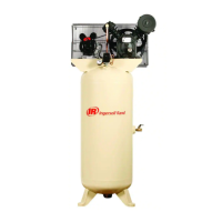
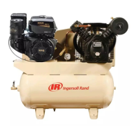
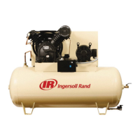
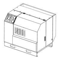
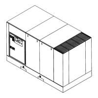
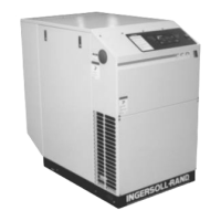
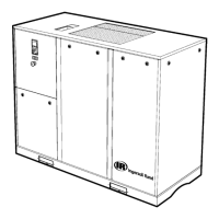
The compressors are typically furnished as compact, self-contained units mounted on an air receiver tank, featuring automatic regulation and driven by an electric motor or gasoline engine. Optional accessories such as an air-cooled aftercooler, low oil level shutdown switch, and automatic drain valve enhance functionality. Bare compressor pumps and baseplate-mounted units are also available.
Usage Features
The manual emphasizes safe operation, starting with a detailed section on safety signal words and general safety rules. Users are warned about inhalation hazards (compressors are not approved for breathing air applications), flammable vapors, hazardous voltage, moving parts, hot surfaces, high-pressure air, risk of bursting, flying debris, and noise hazards. Proper personal protective equipment, such as eye and ear protection, is mandatory.
Selecting an appropriate location is crucial for optimal performance and safety. Electric motor compressors require a clean, dry, well-lighted indoor area with ample space for ventilation and cooling airflow, at least 12 inches (30 cm) from walls. They should not be installed outdoors or in areas exposed to moisture unless specifically protected. For compressors with electric drain valves, the valve should be located in a room or enclosure or at least 18 inches (45 cm) above the floor due to arcing or sparking parts. Gasoline engine compressors must be kept at least 3 feet (1 m) away from building walls and other equipment and should not be operated in confined areas. Ideal operating temperatures are between 32°F and 100°F (0°C and 37.8°C), with recommendations for heated areas or crankcase heaters in colder conditions.
Mounting instructions detail how to secure the compressor to a solid, flat, and level surface. For concrete floors, specific hardware kits and drilling procedures are provided. Vibration isolation mounts or pads, if included or mandated by local codes, must be properly installed to prevent mechanical failure and maintain warranty coverage. Truck bed mounting for gasoline engine compressors also requires secure fastening without stressing the receiver tank.
Air inlet connections require proper filtration to prevent dirt from entering the compressor. If remote air inlet filtration is needed, PVC plastic tubes are recommended, ensuring the line is as short and direct as possible, adequately braced, and covered with a hood if outdoors. Air discharge connections must use suitable air handling parts certified for the maximum working pressure and temperature of the machine, explicitly prohibiting plastic pipe, soldered copper fittings, rubber hose, or lead-tin soldered joints in the compressed air system. If synthetic lubricant is used, all downstream piping and components must be compatible.
Electrical connections for permanently connected electric compressors must be performed by a qualified electrician in compliance with all applicable electrical codes. This includes ensuring compatible voltage, phase, and hertz characteristics, using adequately sized power leads, and installing magnetic starters with thermal overload protection if the motor lacks a reset button. Proper grounding is critical to prevent electrical shock, with ground terminals identified by a symbol or letters.
Operation procedures include daily pre-operation checks such as draining the air tank, checking oil levels, and inspecting air filters. Start-up instructions for electric motor driven compressors involve closing the service valve, applying power, setting the pressure switch to "ON/AUTO" or "ON," and slowly opening the service valve. For gasoline engine compressors, users must release residual tank pressure, turn on the gasoline supply, set the choke to "on," place the unloader lever in the "unload" position, start the engine, and then return the unloader lever to the "load" position after warming up.
The manual also covers pressure switch adjustment for models with adjustable switches, detailing how to set cut-in and cut-out pressures. The starting unloading system, which relieves cylinder pressure for easier starting, is explained, along with pilot valve adjustment procedures to address excessive heat in the pilot valve tube line. An oil consumption check formula is provided to determine acceptable oil usage rates.
Maintenance Features
A detailed maintenance schedule is provided, outlining daily, weekly, monthly, and periodic tasks (3/500 and 12/2000 operating hours/months).
Daily/Before Each Operation:
- Check for oil leaks.
- Check lubricant level and fill as needed.
- Drain receiver tank condensate (manually or via automatic device).
- Check for unusual noise and vibration.
- Ensure beltguards and covers are securely in place.
- Ensure engine (if supplied) is filled with fuel and lubricant according to manufacturer's recommendations.
- Ensure the area around the compressor is free from debris and flammable materials.
- Observe safety/relief valve operation and replace if they do not operate freely.
Weekly:
- Inspect air filter element(s) and clean if necessary.
- Inspect for air leaks by squirting soapy water around joints.
- Check tightness of screws and bolts and tighten as needed.
- Inspect drive belts and adjust if necessary.
- Clean the exterior of the compressor.
Monthly (Every 30 Days):
- Change petroleum lubricant while the crankcase is warm.
- Drain compressor oil and clean the oil sight glass.
- Install a maintenance pak (if applicable).
Periodic (3/500 and 12/2000 operating hours/months):
- Change synthetic lubricant while the crankcase is warm.
- Replace filter element.
The manual provides specific instructions for filter inspection and cleaning, including how to remove, clean, and replace the filter element. Oil change procedures involve removing the drain plug, allowing lubricant to drain, replacing the plug, and refilling according to the OPERATION section.
Belt adjustment instructions detail how to check and tension drive belts, which is crucial for preventing motor overload, excessive vibration, and premature belt/bearing failure. This involves using a straight edge and a tension gauge to measure deflection and force, comparing readings to the provided BELT TENSION TABLE. Proper pulley/sheave alignment is also emphasized.
Electric drain maintenance includes a daily check for proper valve operation and cleaning the filter screen if needed. Monthly (every 30 days) cleaning of the filter screen is also recommended. Detailed steps are provided for cleaning the filter screen, including isolating the valve, venting pressure, removing the plug, cleaning the screen, and reassembling.
Tank inspection is highlighted as critical for safety. The life of an air receiver tank depends on operating conditions, ambient environment, and maintenance. Ingersoll Rand recommends a certified tank inspection within the first five years of service. Tanks not inspected within 10 years must be taken out of service until inspected. Users are warned that failure to replace a rusted tank can lead to rupture or explosion, causing severe injury or death, and that tanks should never be modified or repaired.
A troubleshooting guide is included to help users identify and resolve common issues, such as abnormal piston wear, air delivery drops, excessive noise, motor overload, and oil leaks. It lists potential causes and corresponding actions. A separate troubleshooting section for electric drain valves addresses issues like the valve not closing or the timer not activating, providing solutions like cleaning components or replacing parts.
The manual also includes diagrams and tables, such as a fastener torque table for various bolts and screws, and a belt tension table with deflection and tension values for different models and belt types. Electrical wiring diagrams for single-phase and three-phase units are provided, along with instructions for connecting line power to the starter and proper grounding.